Installation
I would appreciate if you'll grab your copy of the plugin from the kaktak.gumroad.com/l/moconnections
Last update: version 1.6.1 from May-26-2025
Extract plugin into application plugins folder or into the user's plugin folder (see below)
Restart Cinema4D app and enjoy
Plugin is compatible with Maxon Cinema4D R20 — 2024.2
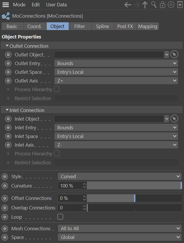
Object properties
Outlet/Inlet Object
MoGraph object source
-
Matrix
-
Cloner
-
Fracture
-
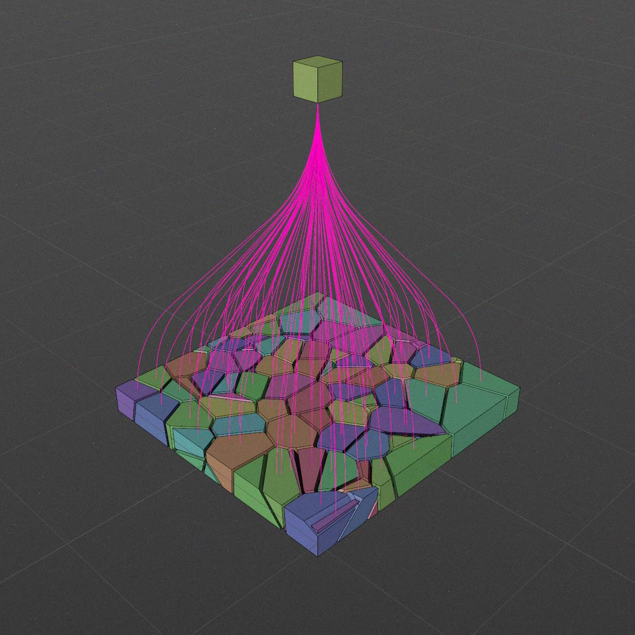
Voronoi Fracture
Outlet/Inlet Entry
MoGraph instances are processed to create entries for the connections.
This option affect entries positions and connections count.
-
Pivot
-
Bounds
-

Polygon Center
-
Vertex
Pivot
Instance's pivot or Object Axis Center
Bounds
Instance's bounding box takes in respect. Specific box face is based on Outlet/Inlet Axis
Polygon Center
Instance's polygon centers used as a connection entries. Polygon selections also might be used as a restrictions.
* Only applicable if instance is a polygon object.
Vertex
Instance's vertices used as a connection entries. Point selections also might be used as a restrictions.
* Only applicable if instance is a mesh or spline object.
Outlet/Inlet Space
Connections out/in points are having tangents.
This option affect how Outlet/Inlet Axis is calculated.
-
Entry's Local
-

Entry's Mesh Normal
-

World
-
Generator's local
Entry's Local
Instance's local space.
Entry's Mesh Normal
Instance's polygon normals. Can be used with Polygon Center and Points entries.
* Only applicable if instance is a polygon object.
World
World space.
Generator's local
Tangents are calculated in plugin's space.
Outlet/Inlet Axis
Tangent vector based on entry type and space.
-
X+
-
X-
-
Y+
-
Y-
-
Z+
-
Z-
-
Aim Opposite
-
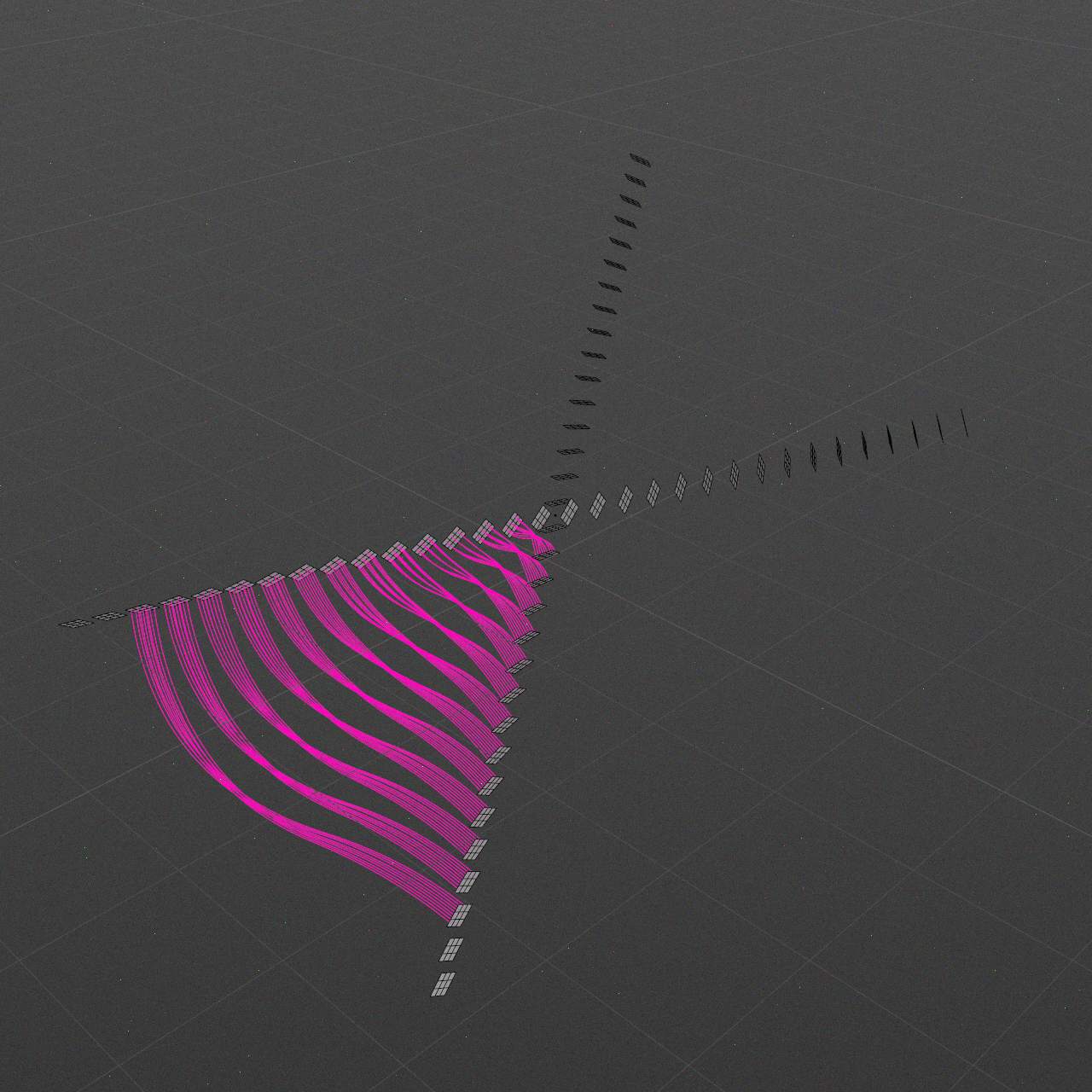
Mirror Opposite
X+, X-, Y+, Y-, Z+, Z-
Axis direction (and bounds point in case of Bounds entries) in the corresponding Outlet/Inlet Space.
Aim Opposite
Aim corresponding opposite instance, so outlet aims inlet, and inlet aims outlet.
Mirror Opposite
Creates inverted tangent of corresponding opposite instance.
If opposite tangent is also Mirror Opposite it would have same effect as Aim Opposite.
Process Hierarchy
If checkbox is disabled only top-level object of the instance would be used as an entry.
If checkbox is enabled full hierarchy of the instance would be used as an entry.
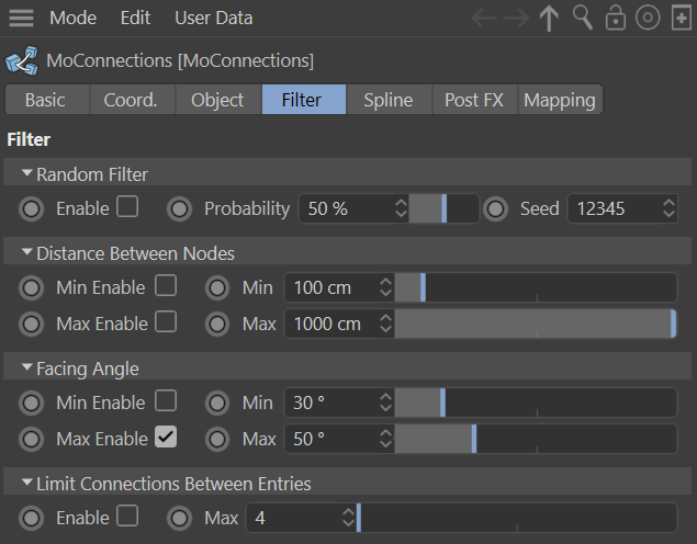
Restrict Selection
Restrict to provided polygon/point selection in case of Polygon Center/Points entry type correspondingly.
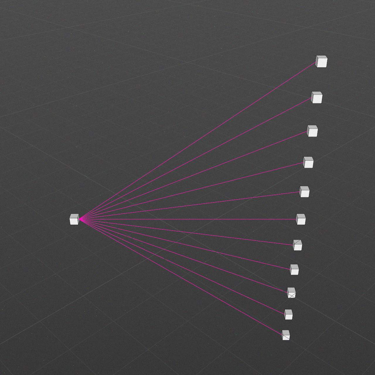
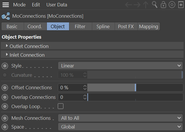
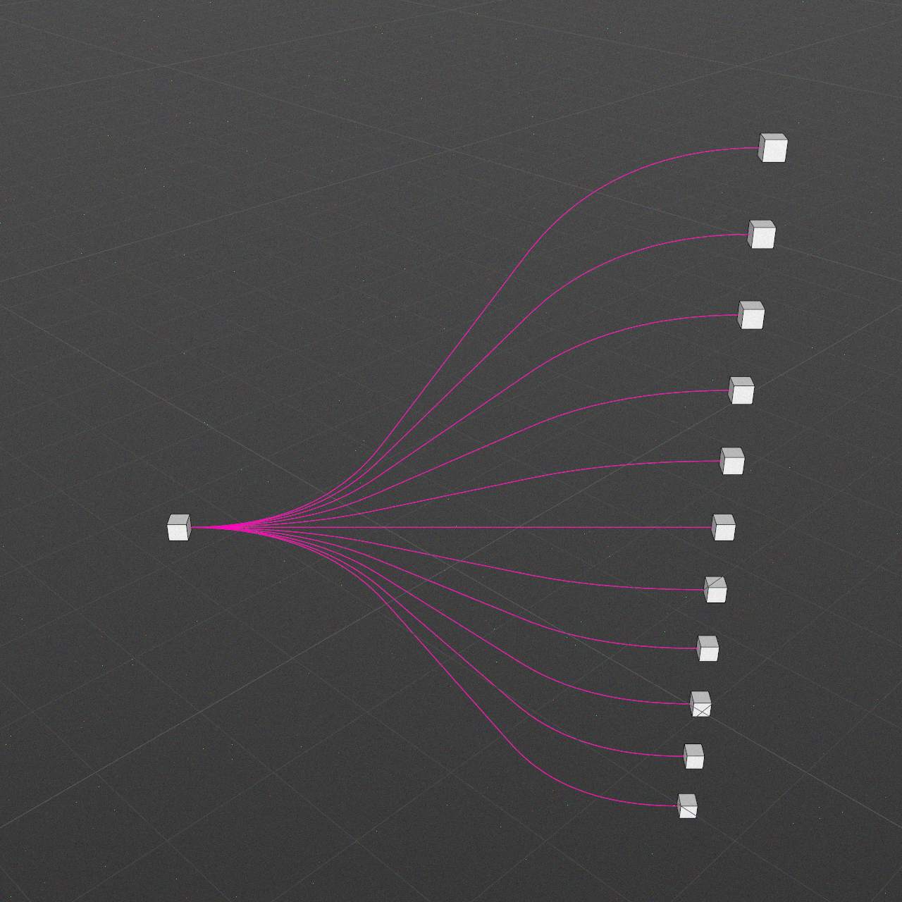
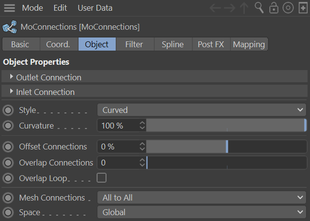
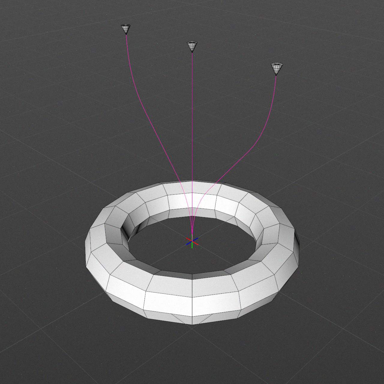
Style
Connection spline shape
Linear
Straight line.
Curved
Special curved shape, good starting point.
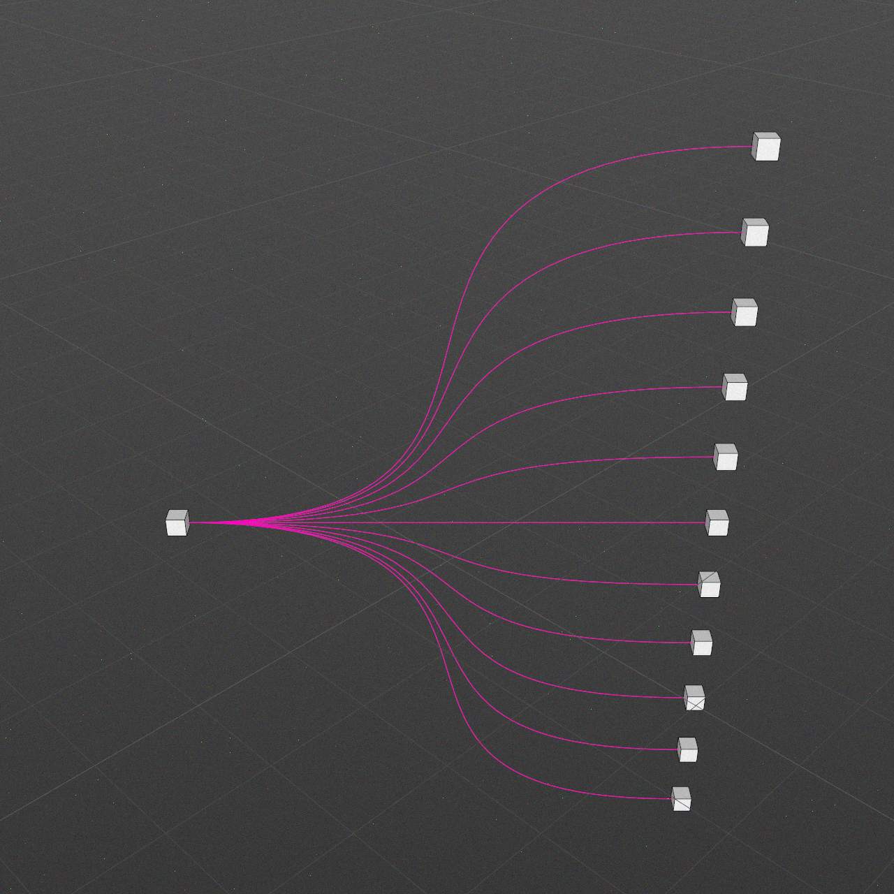
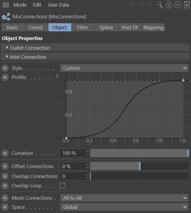
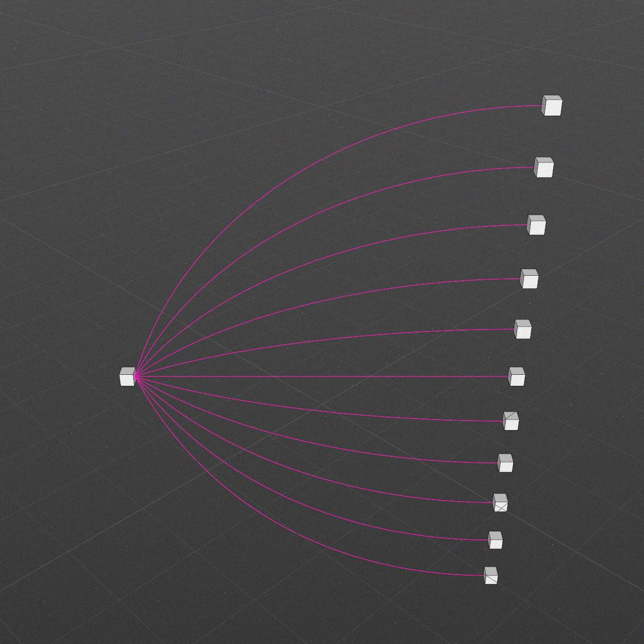
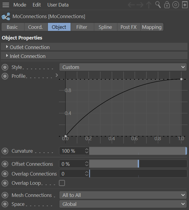
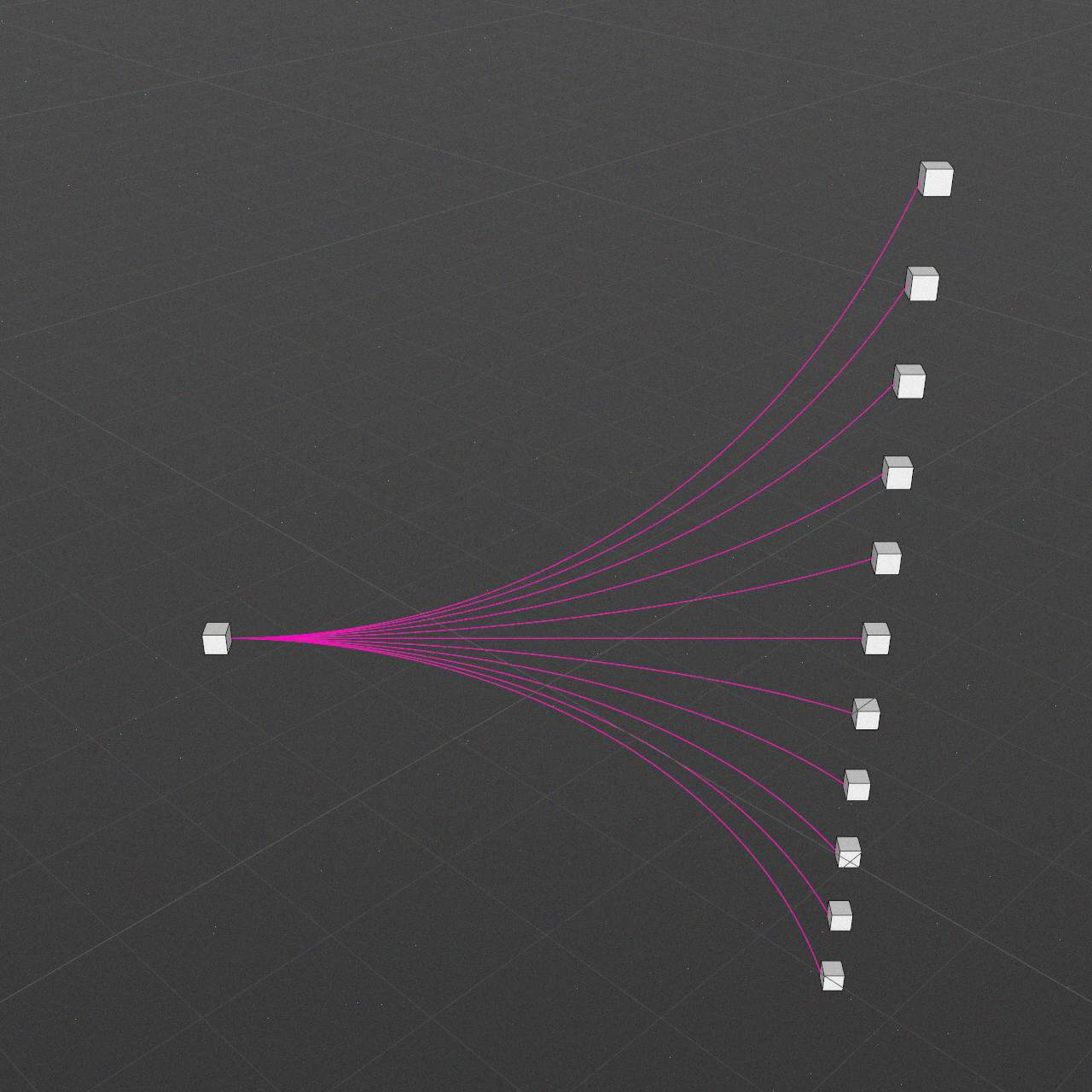
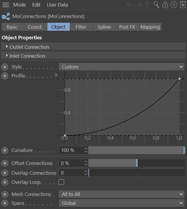
Custom
Custom curve shape. When chosen, additional Profile field appears.
Profile
Activates when Custom option of Style is selected.
Horizontal axis corresponds to spline path.
Vertical axis corresponds to alignment along outlet/inlet normals.
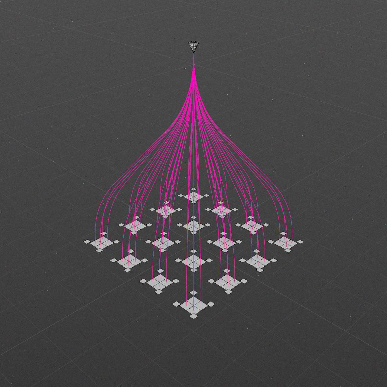
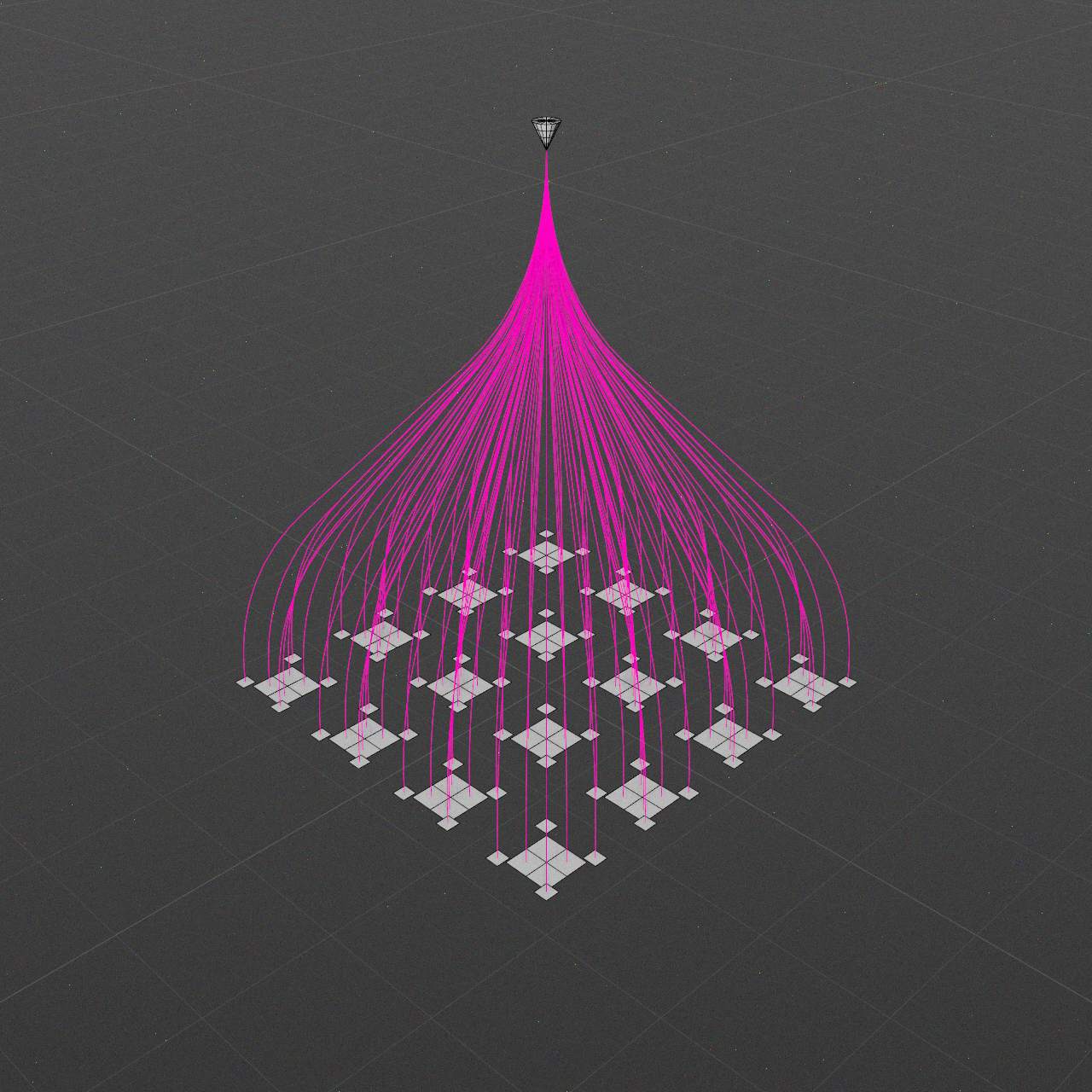
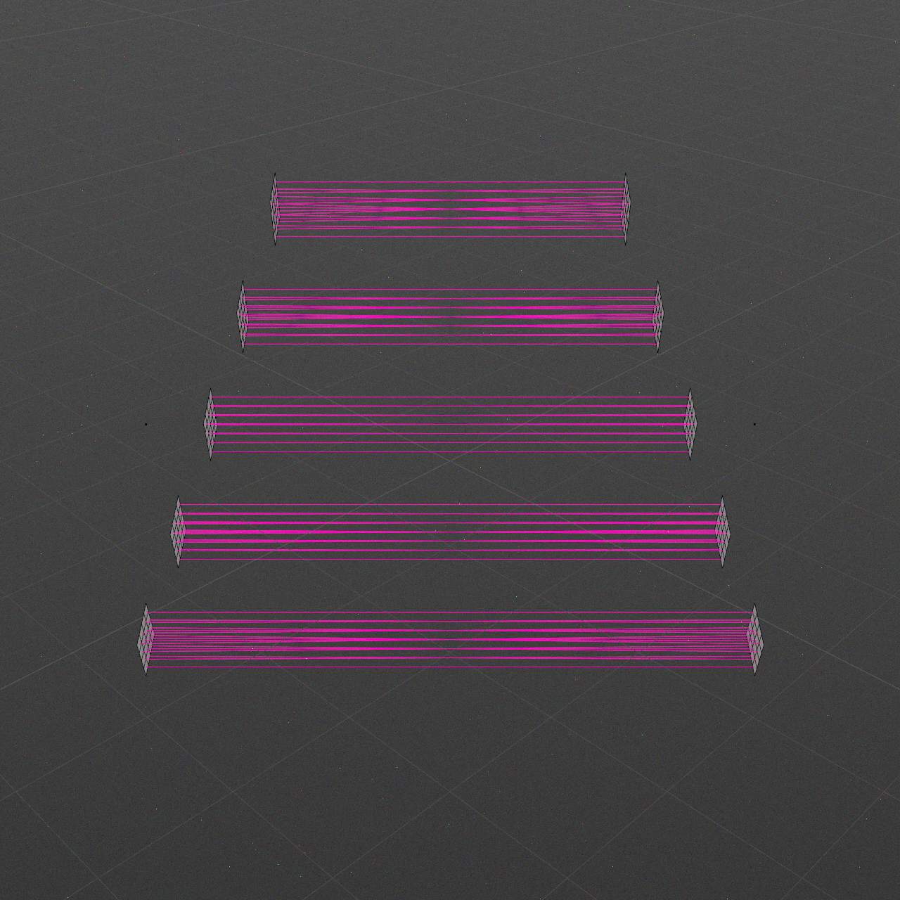
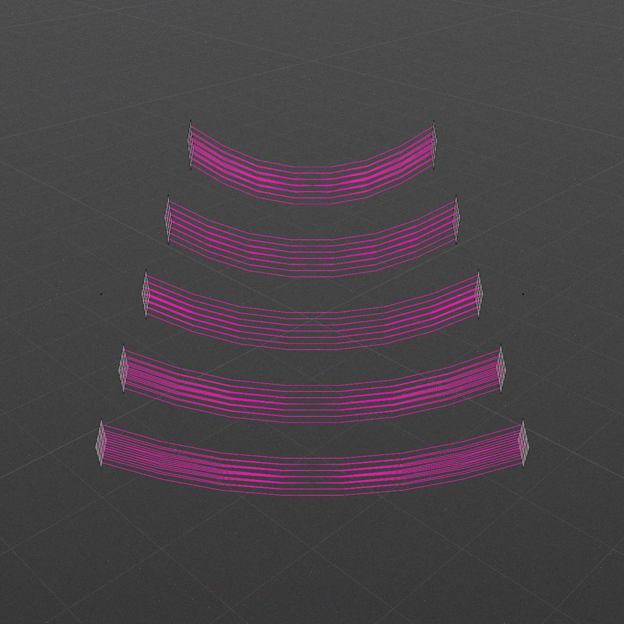
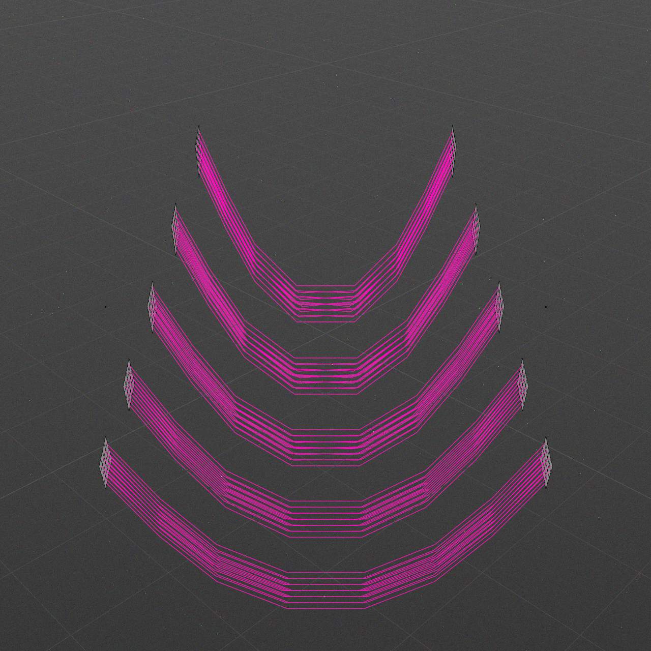
Curvature
0..+∞ %
Spline shape curvature adjust option.
Value of 0% makes curved spline as linear.
Value of greater than 100% makes curved spline looks much curved.
-
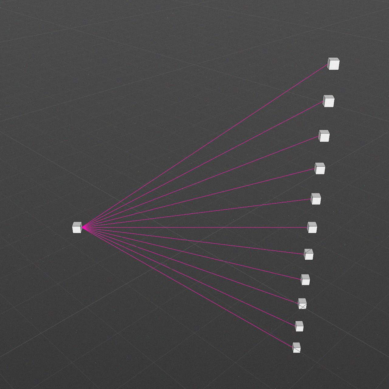
Curvature: 0
-
Curvature: 50
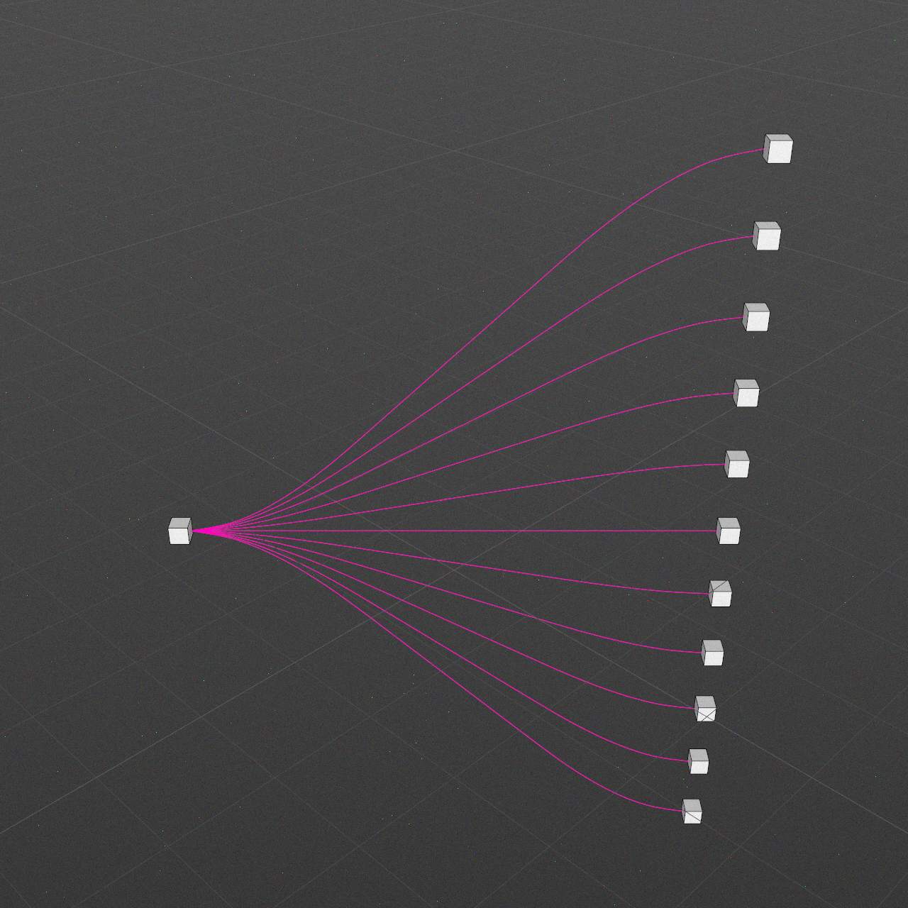
-

Curvature: 100
-
Curvature: 200
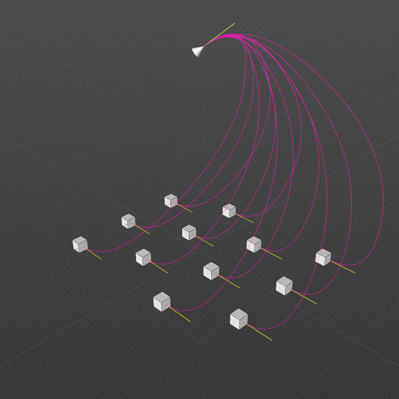
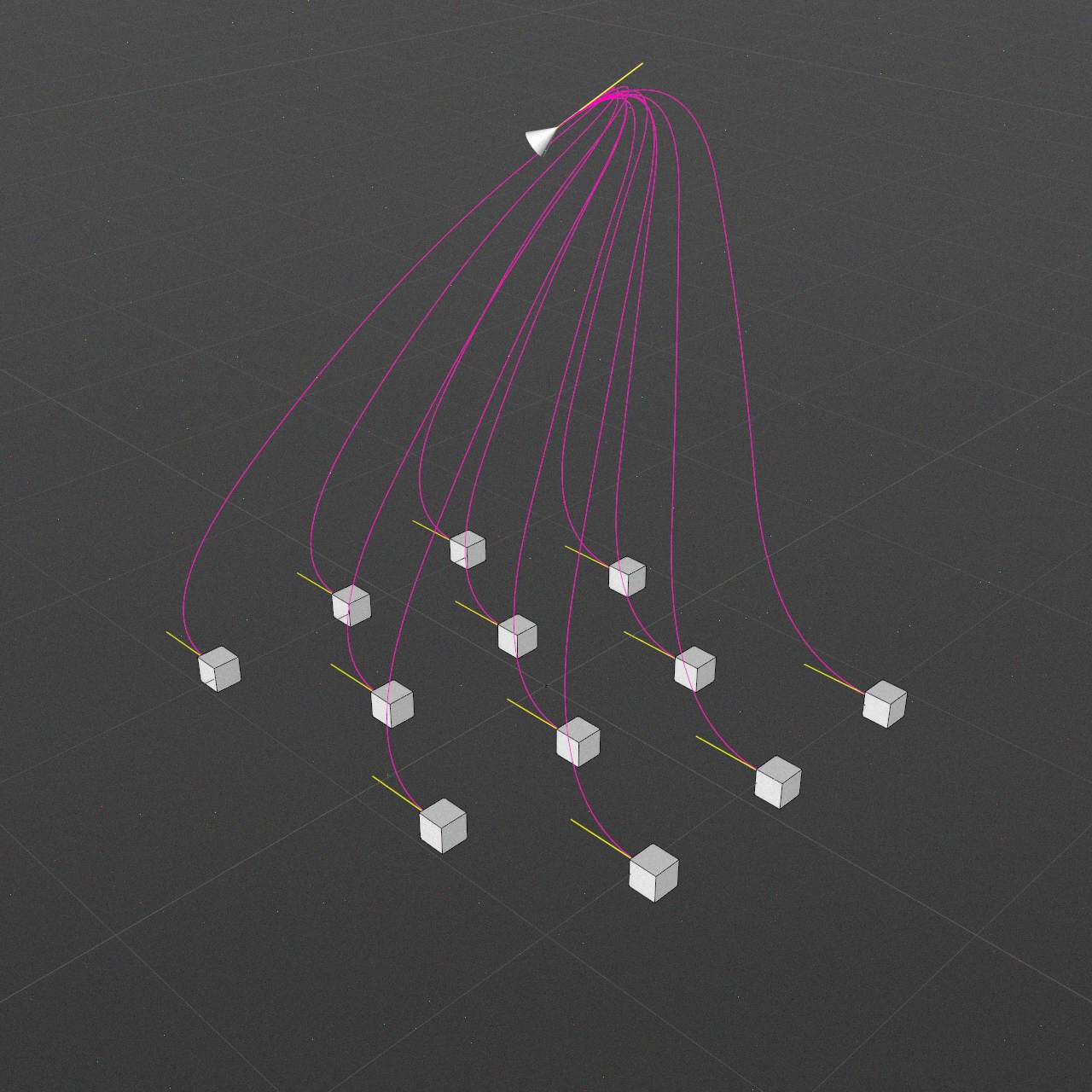
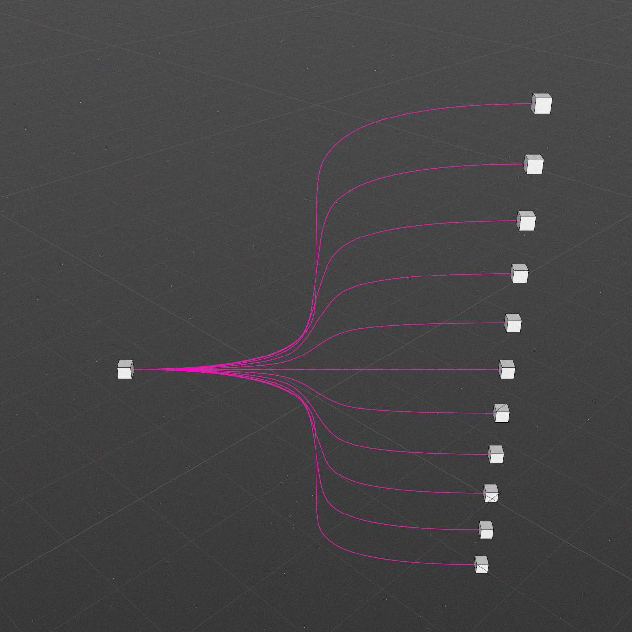
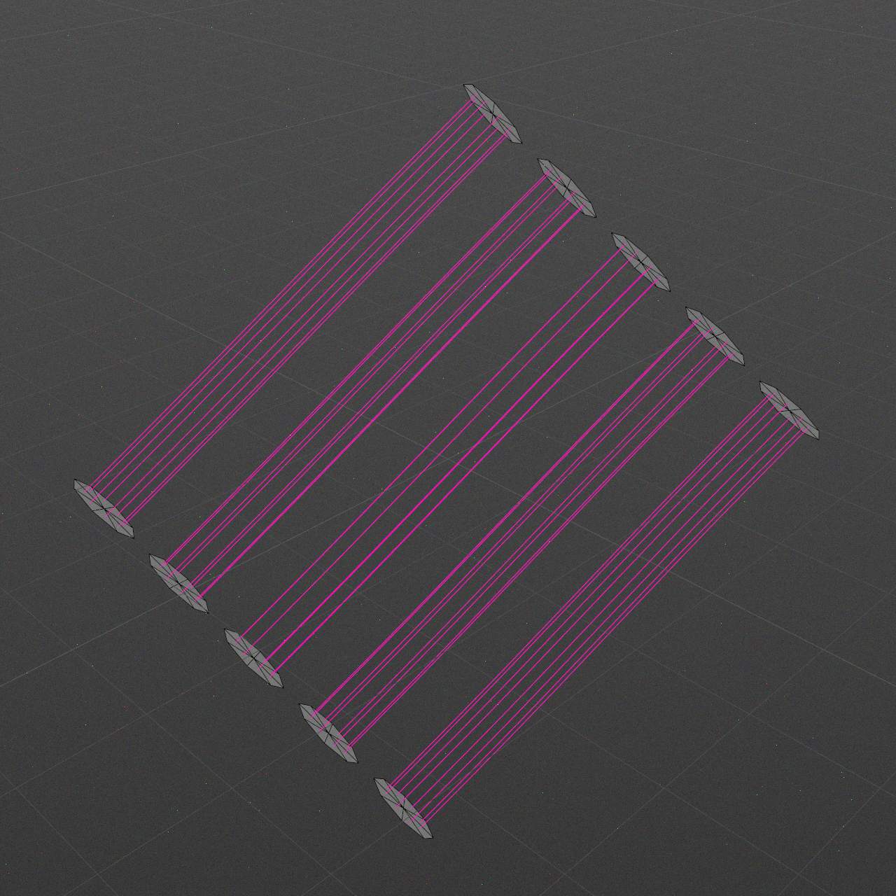
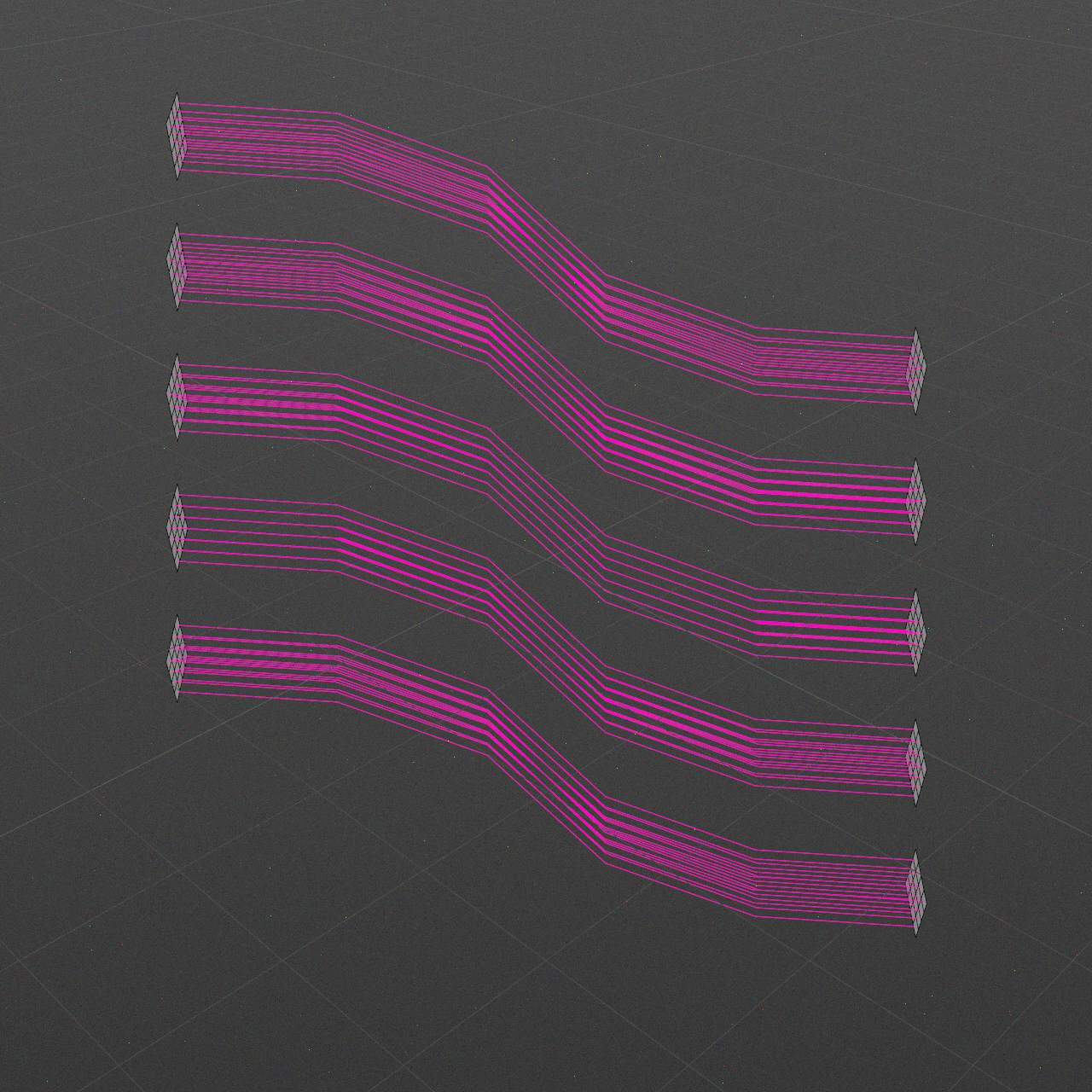
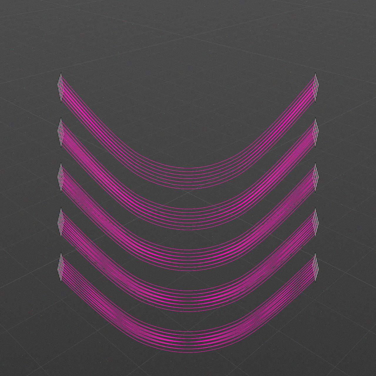
Offset Connections
-∞..+∞ %
Offset outlet/inlet instance indices mapping.
-
Offset: 0%
-
Offset: -20%
-
Offset: 20%
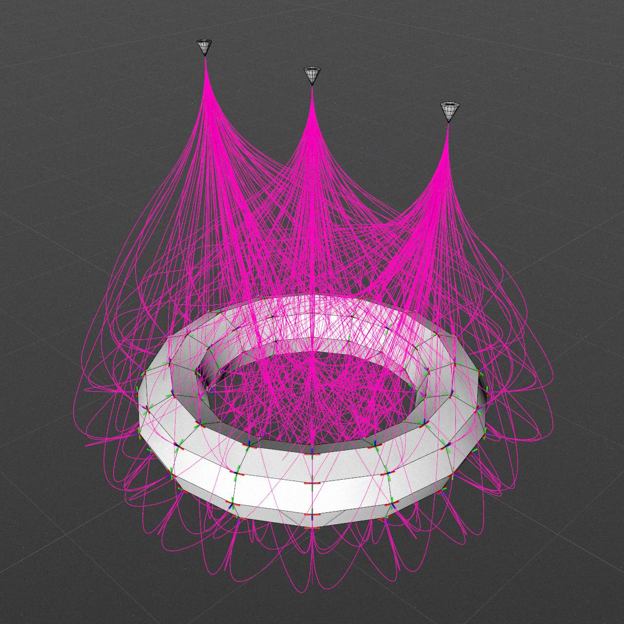
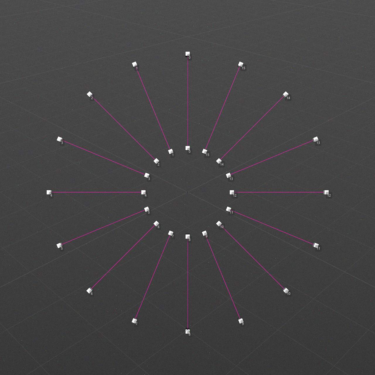
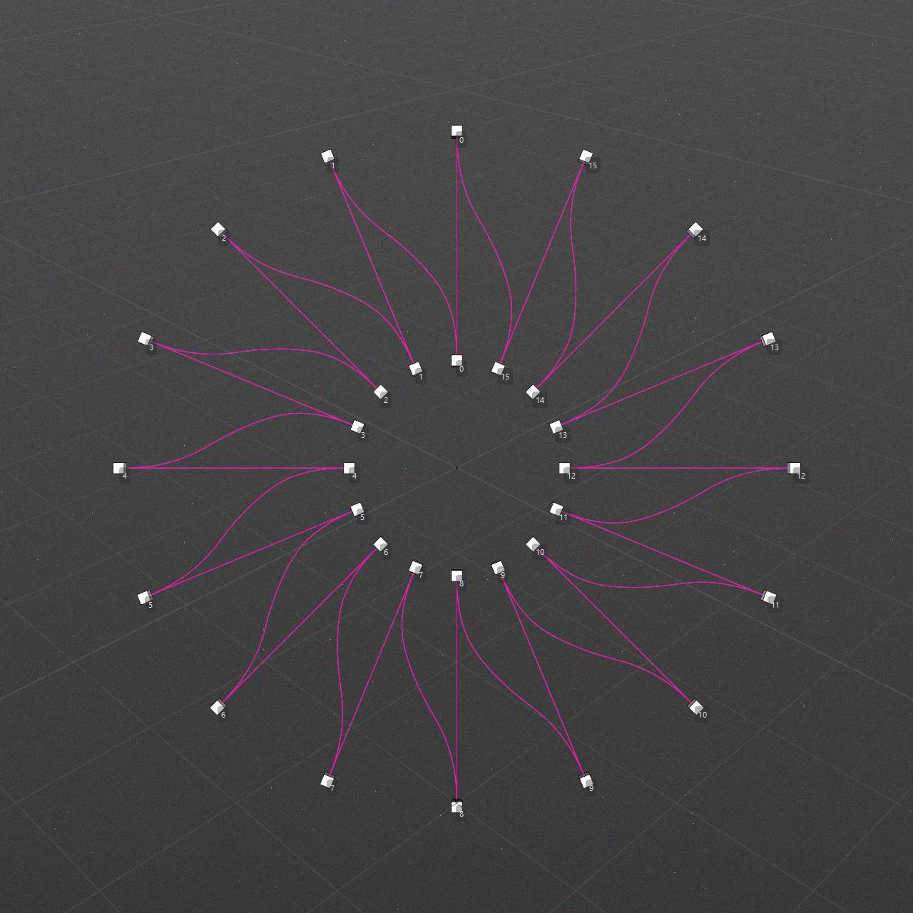
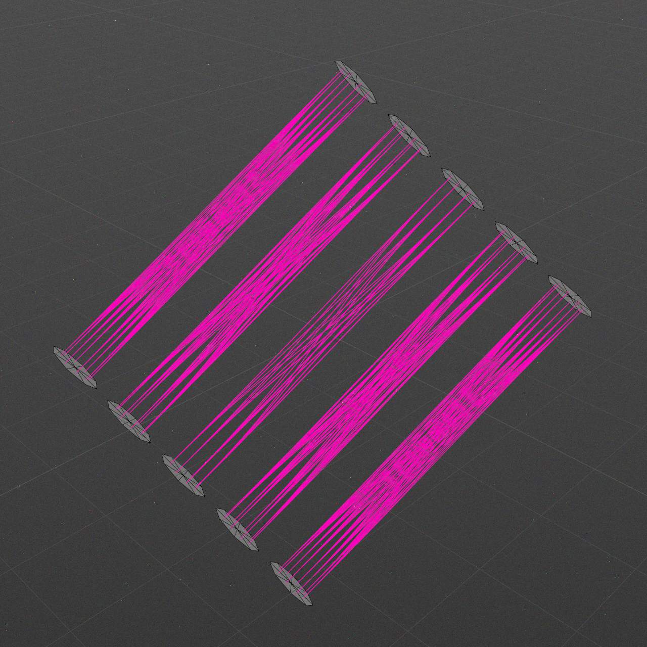
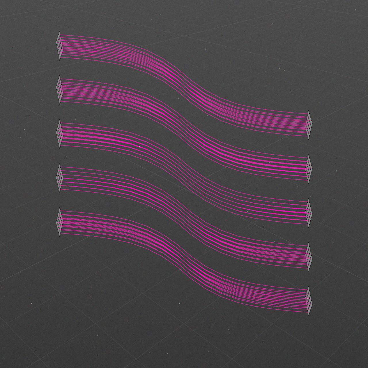
Overlap Connections
0..+∞
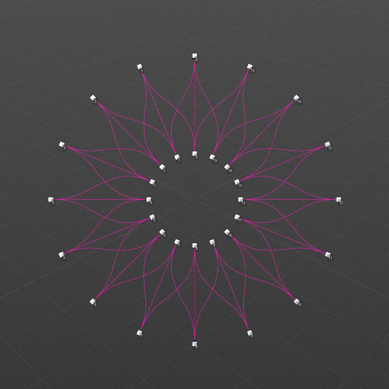
Each outlet might be additionally connected with neighbor instances.
Value of 1 creates additional connection with next instance.
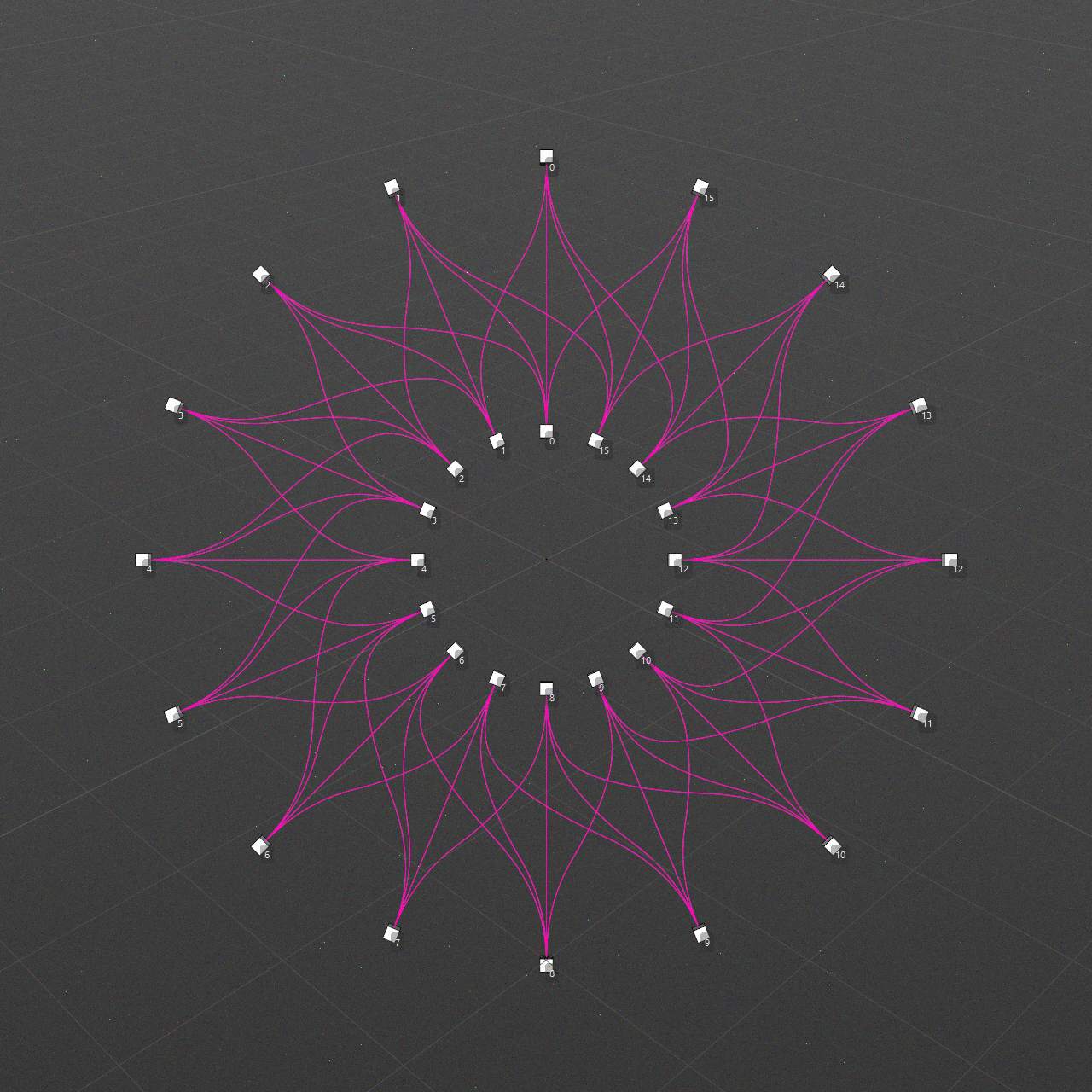
Value of 2 creates same connection as above, plus additional connection with previous instance.
Next steps follows same logic.
-
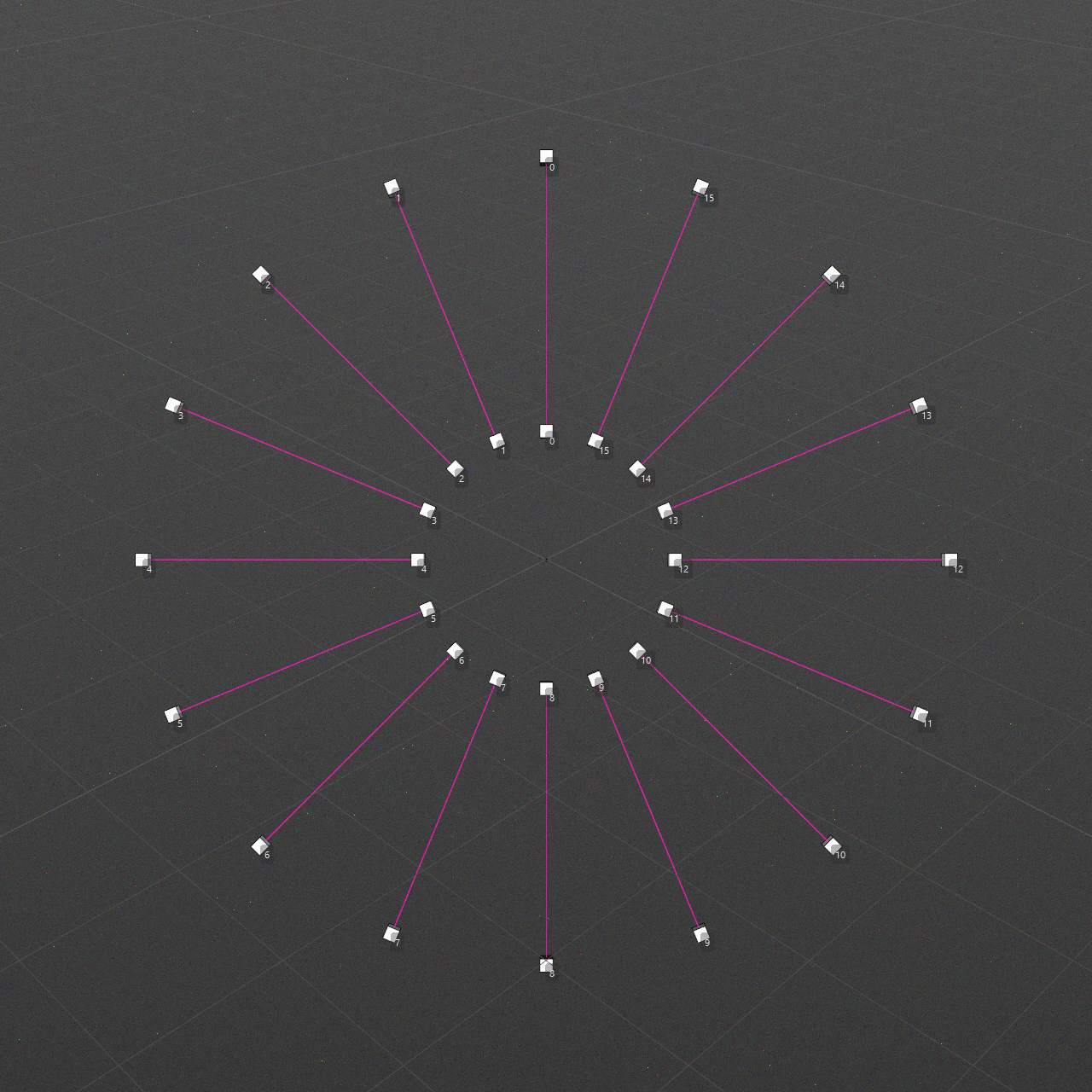
Overlap: 0 / Loop: False
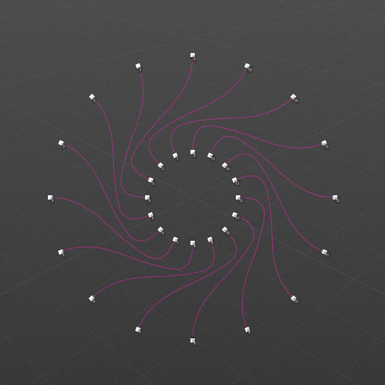
-
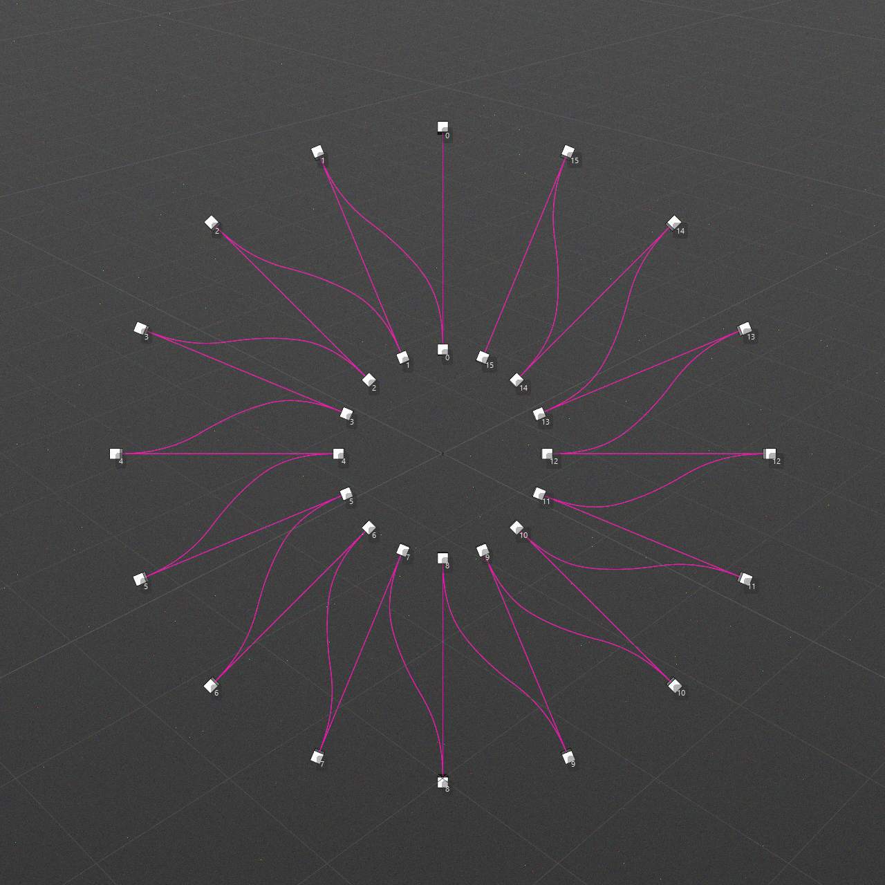
Overlap: 1 / Loop: False
-
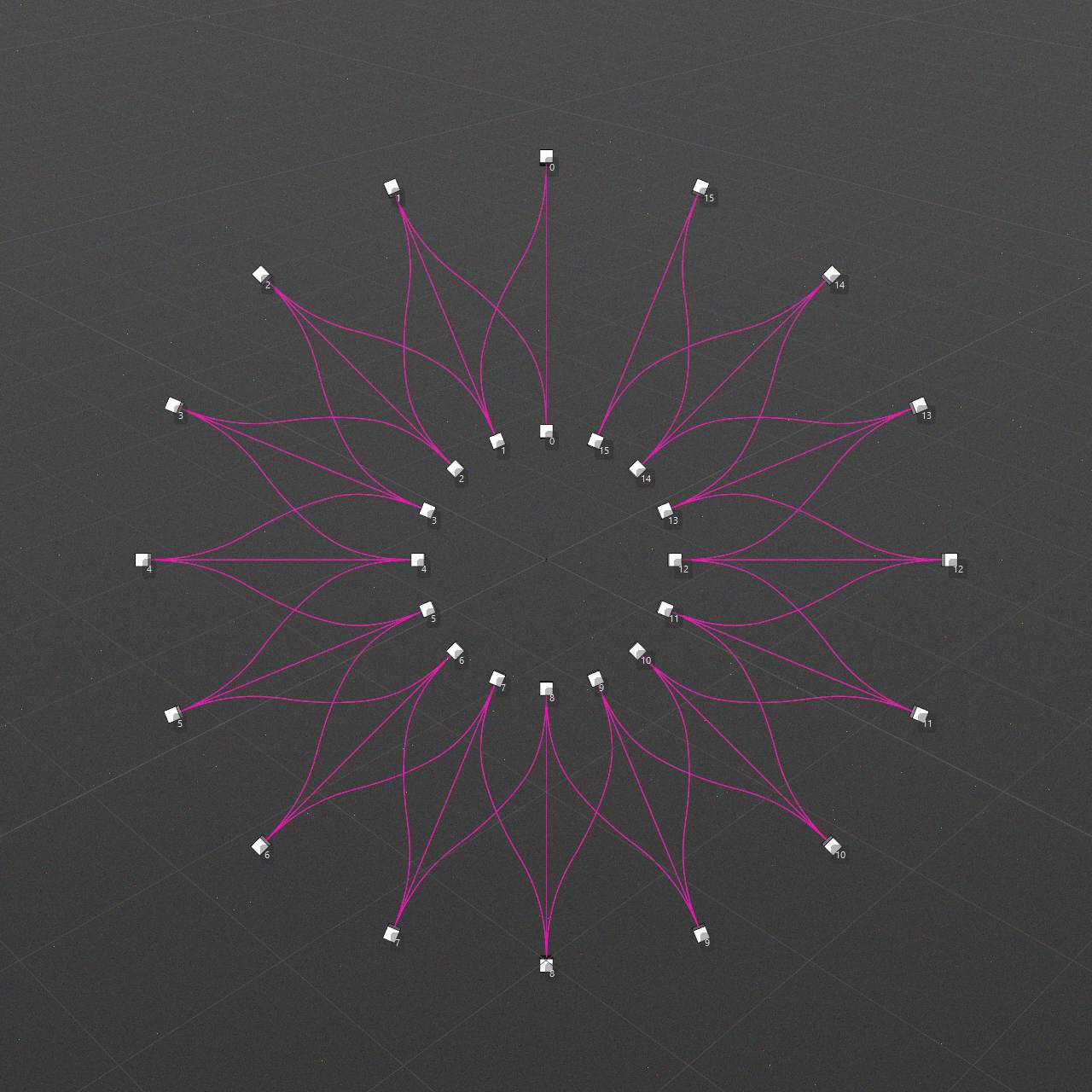
Overlap: 2 / Loop: False
-
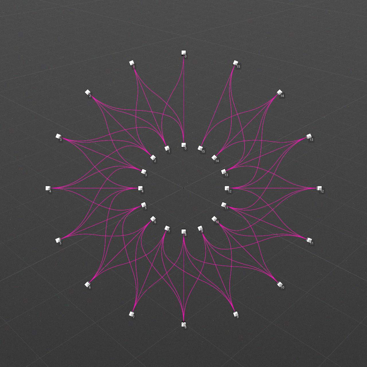
Overlap: 3 / Loop: False
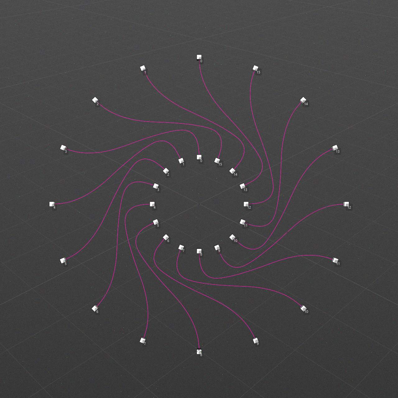
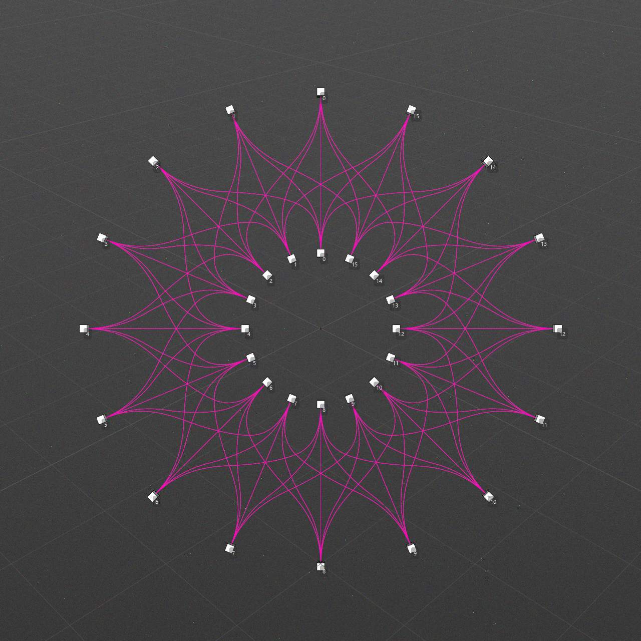
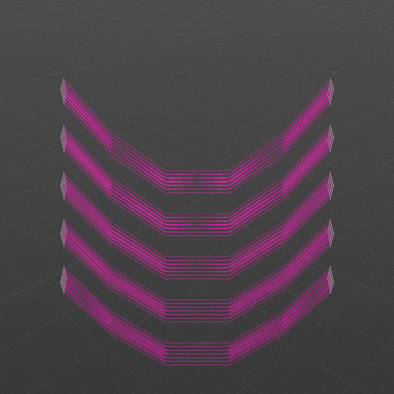
Loop
Affect Offset Connections and Overlap Connections behavior.
If disabled then entries calculations are clipped by first and last instance indices.
If enabled then entries calculations uses math modulo.
-
Overlap: 1 / Loop: True
-
Overlap: 2 / Loop: True
-
Overlap: 3 / Loop: True
-
Overlap: 4 / Loop: True
Mesh Connections
This setting affect case when both outlet and inlet entries uses Polygon center or Points type.
-
All to All
-
Order groups
All to All
All polygons/points of outlet instance connect to all polygons/points of inlet instance.
Order groups
All polygons/points of outlet and inlet instances connects by order groups.
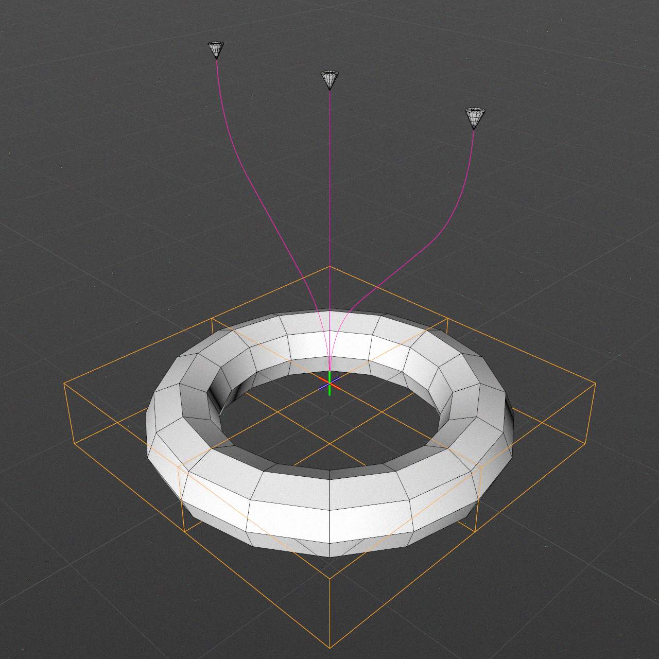
Space
Splines generating space
Local
Splines are generating in local space of MoConnections object, so it would be affected by its transform.
Global
Splines are generating in world space, so it would not be affected by MoConnections transform.
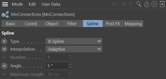
Spline
Standard spline properties
Type
Linear
This simplest of all the spline types connects the vertices, which define the polygon, with straight, directly connected lines. You can use these splines to create angular objects or to simulate sharp jerky movements for animation.
Cubic
This kind of spline has a soft curve between vertices. The interpolated curve passes directly through the vertices. Looking at the two points at the top right of the diagram, you can see that the curve bulges more than is probably required. This behavior is called overshooting, and it often appears with closed curvatures. This becomes clearer when you compare this section of the curve with the same section of the curve with Akima interpolation.
Akima
This spline type creates a soft curve between vertices. The interpolated curve always passes directly through the vertices. Overshooting does not happen with this type of curve. Akima interpolation adheres very closely to the path of the curve directly between the vertices but, because of this, it can sometimes appear somewhat hard. If this is not required, you should use Cubic interpolation.
B-Spline
This kind of spline also creates a soft curve between the vertices. However, the curve does not pass directly through the vertices. This produces a very smooth curve. The vertices control only the approximate path of the curve. Distant points have less influence on the curve than those lying closer together.
Bezier
This spline type creates a soft curve path between the vertices, which can be controlled very precisely. The interpolated curve always passes through the vertices. Overshoot does not happen.
Interpolation
Here you can define how the spline is further subdivided with intermediate points. This affects the number of subdivisions created when using the spline with Generator objects.
None
This method of interpolation locates points only at the vertices of a spline, using no additional intermediate points. You cannot enter values into the Number or Angle boxes. For B-splines, the vertices, and therefore points, might not be located on the spline curve.
Natural
This interpolation type first locates points at spline vertices. In the case of B-splines, points are located at positions on the spline curve closest to the spline vertices. Number (N) corresponds to the number of intermediate points between vertices. The points are positioned closer together on areas of the spline with more curvature.
You cannot enter values into the Angle box.
Uniform
This interpolation subdivides the spline so that the distance between any two consecutive points, as measured along the spline curvature, is constant. One point is always located at the beginning vertex. For open splines, a point is also located at the ending vertex. Other points generally do not coincide with vertices.
You cannot enter values into the Angle box.
Adaptive
This interpolation type sets intermediate points whenever the angle deviation of the curve is larger than the value given in Angle. The points of the resulting curve pass through the vertices. If a spline has several segments, then the value of Angle will apply to each segment.
The Adaptive method gives the best results in rendering, hence it is the default interpolation method.
You cannot enter values into the Number box.
Subdivided
Subdivided is similar to Adaptive. Additional intermediate points will be added until the intermediate segments are shorter than the defined Maximum Length, i.e., the point intervals will not necessarily be equal to the maximum length. Lower values will result in higher quality, along with the disadvantages of working with a high number of points - slower refresh times in the editor view, etc.
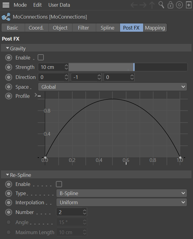
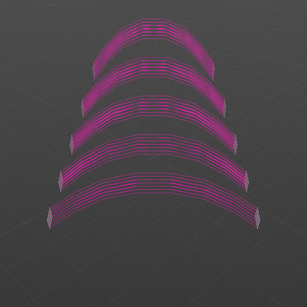
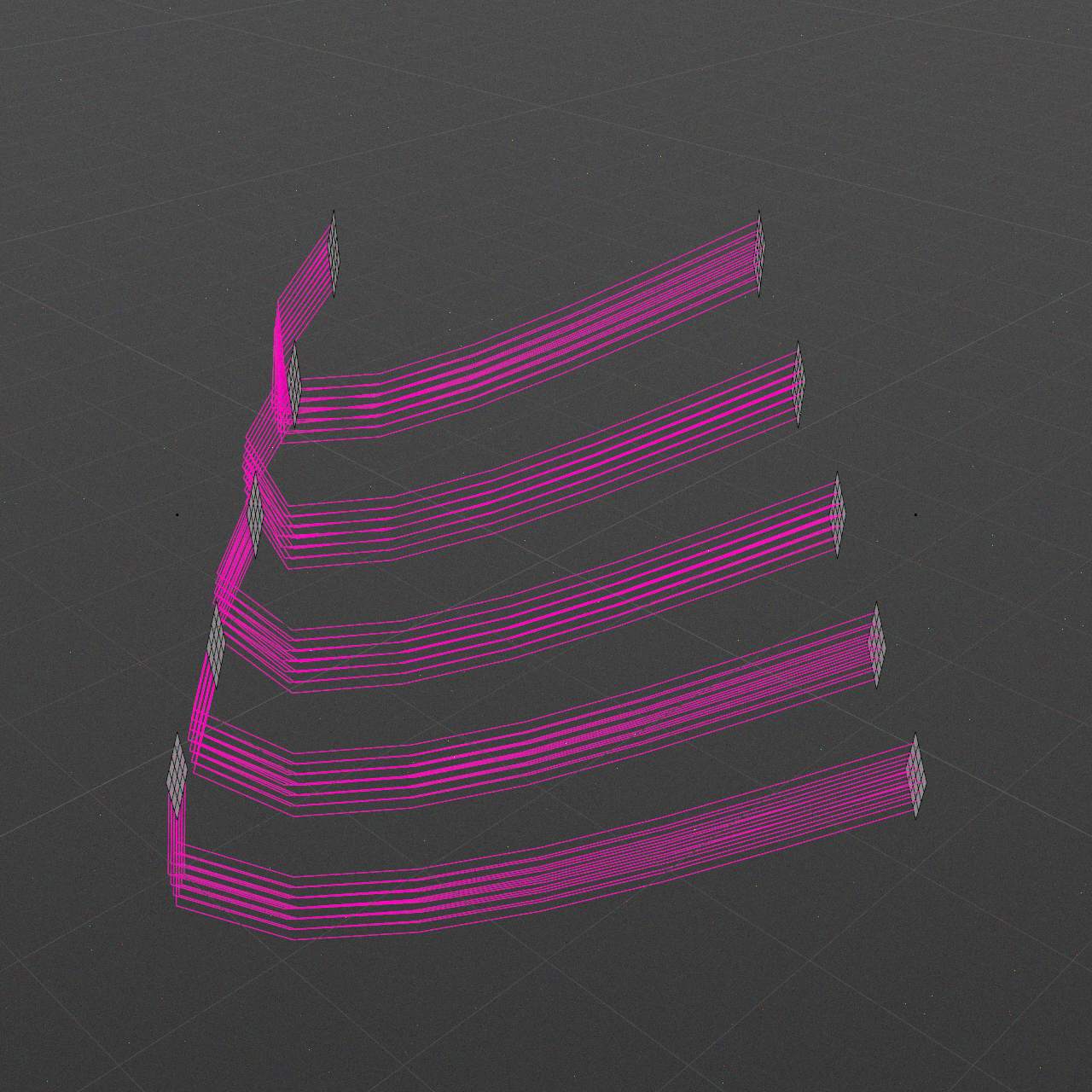
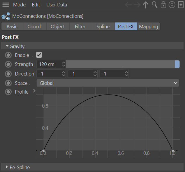
Post FX
Post FX are operating over connection splines to bring some art-direction to the final look.
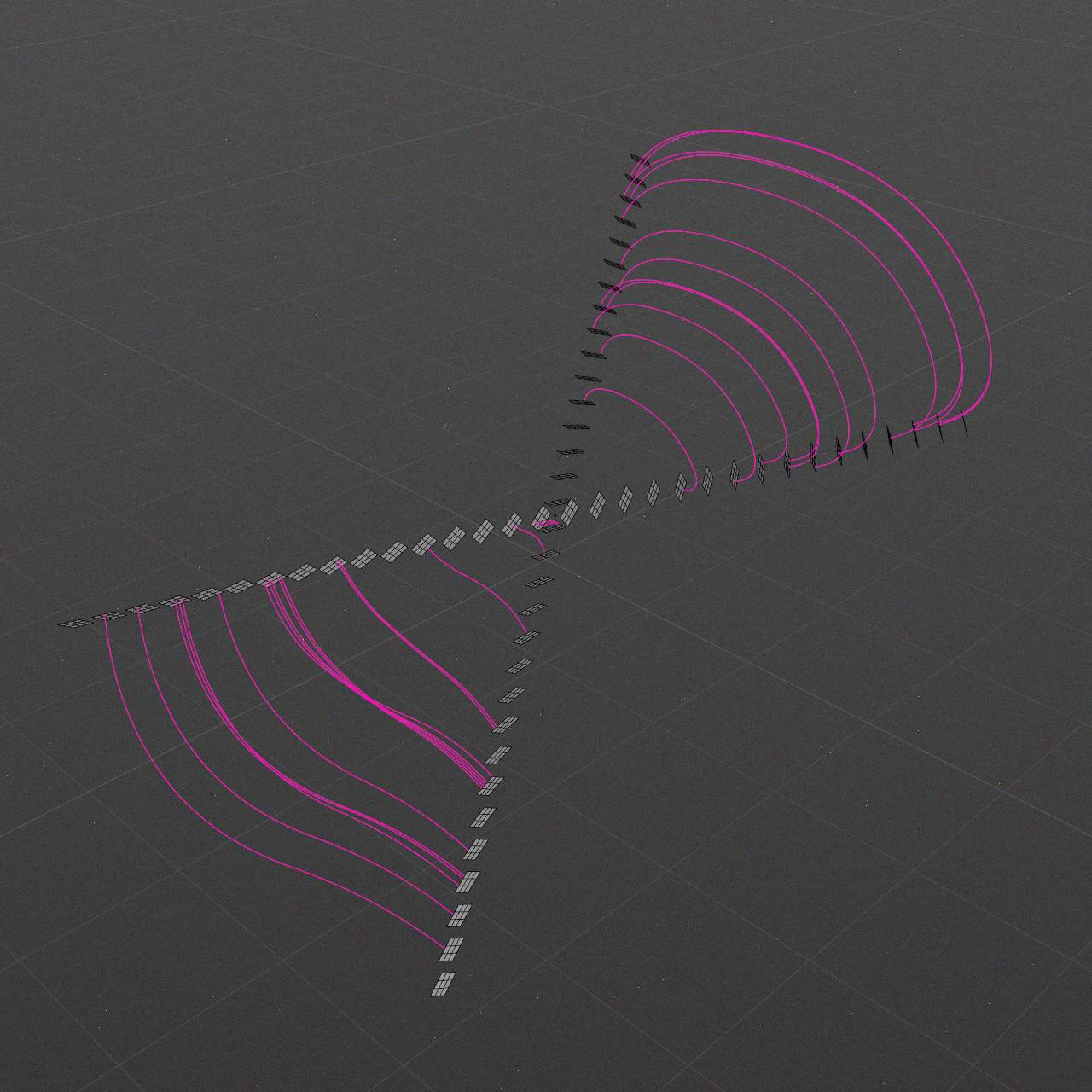
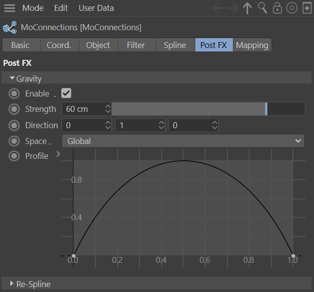
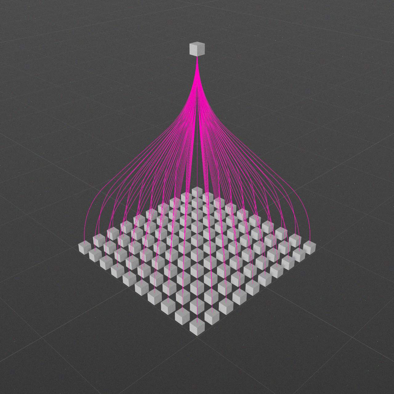
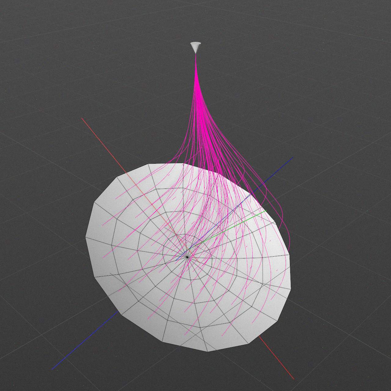
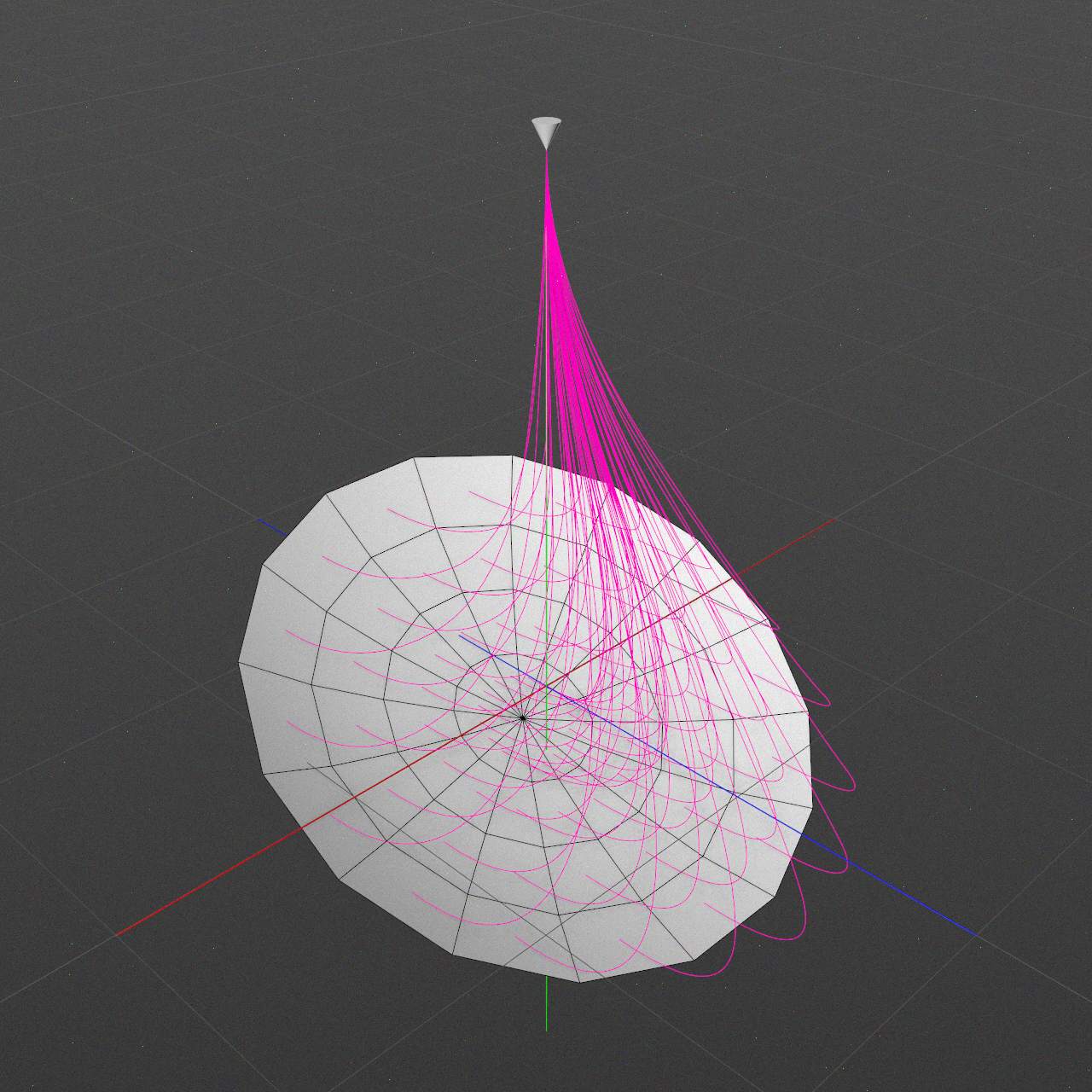
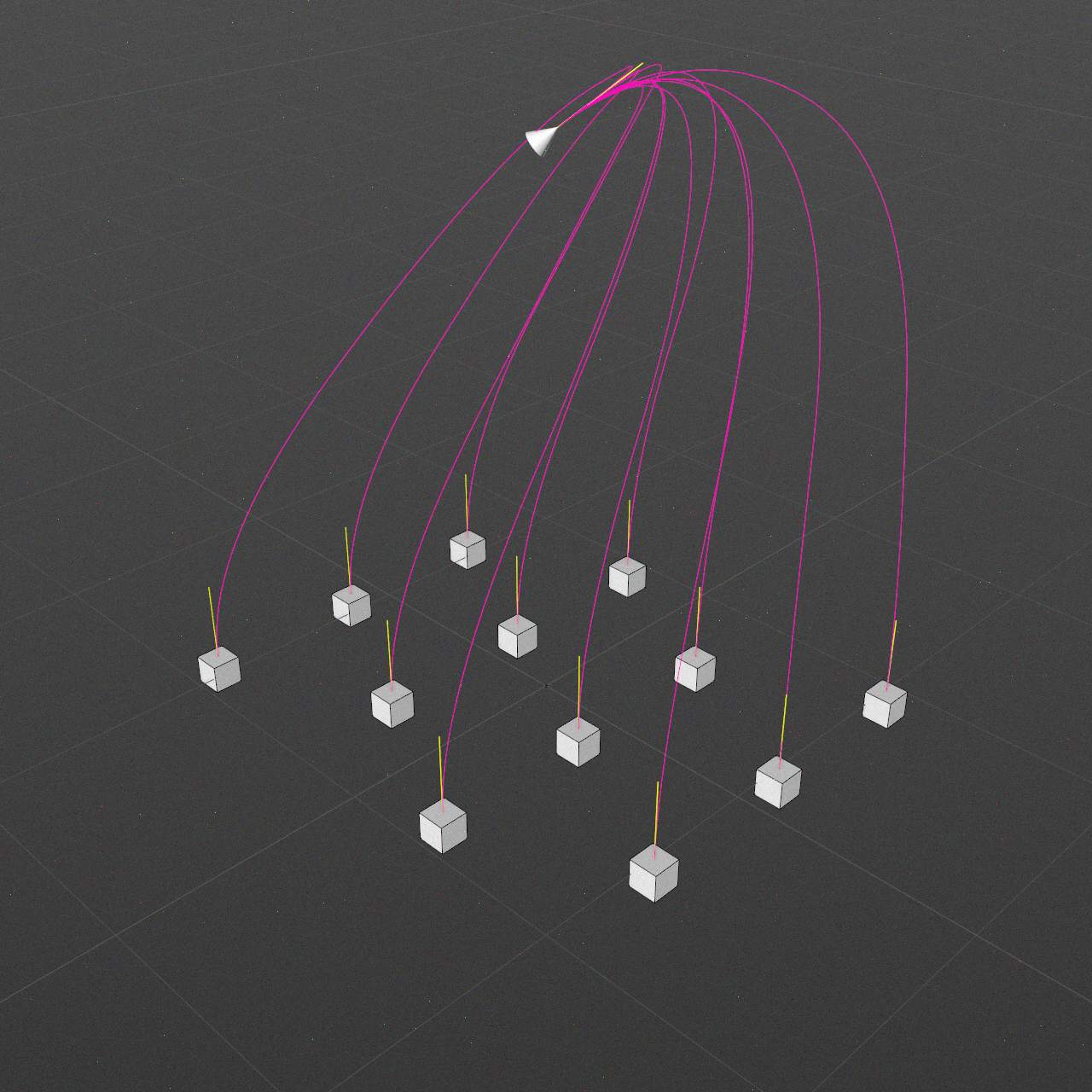
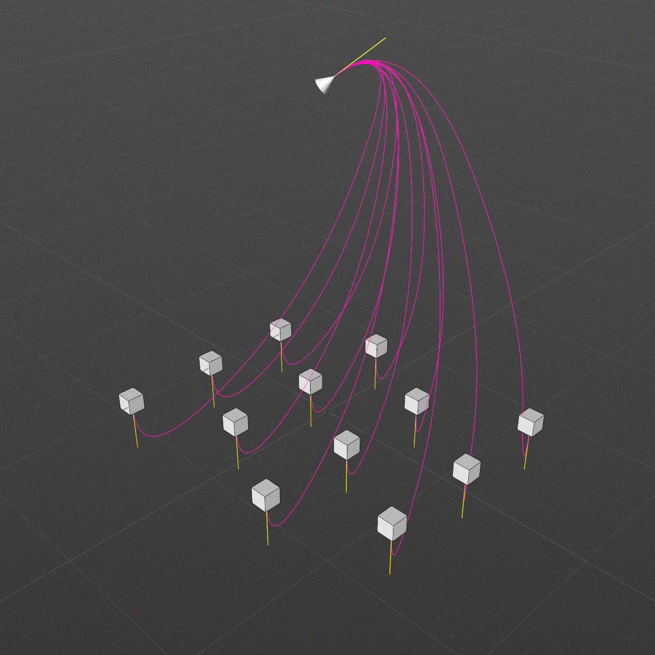
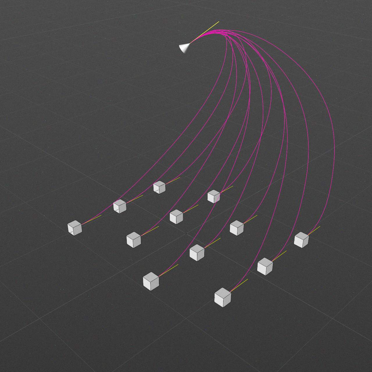
Gravity
Enable
Strength
-∞..-∞ m
Direction
Vector
Space
Local (Generator) / World space
Profile
This graph allows to finetune gravity curvature. Keep first/last points at the bottom corners of the graph to keep start/end spline points near their entries.
-
Disabled / Strength: 0
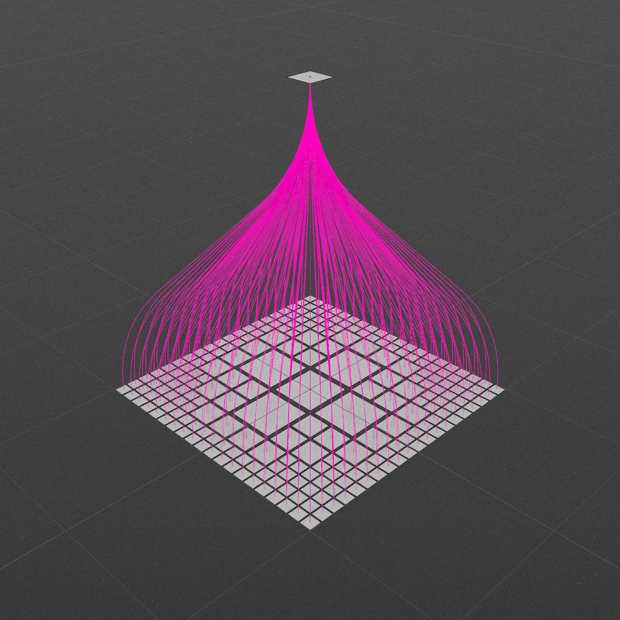
-
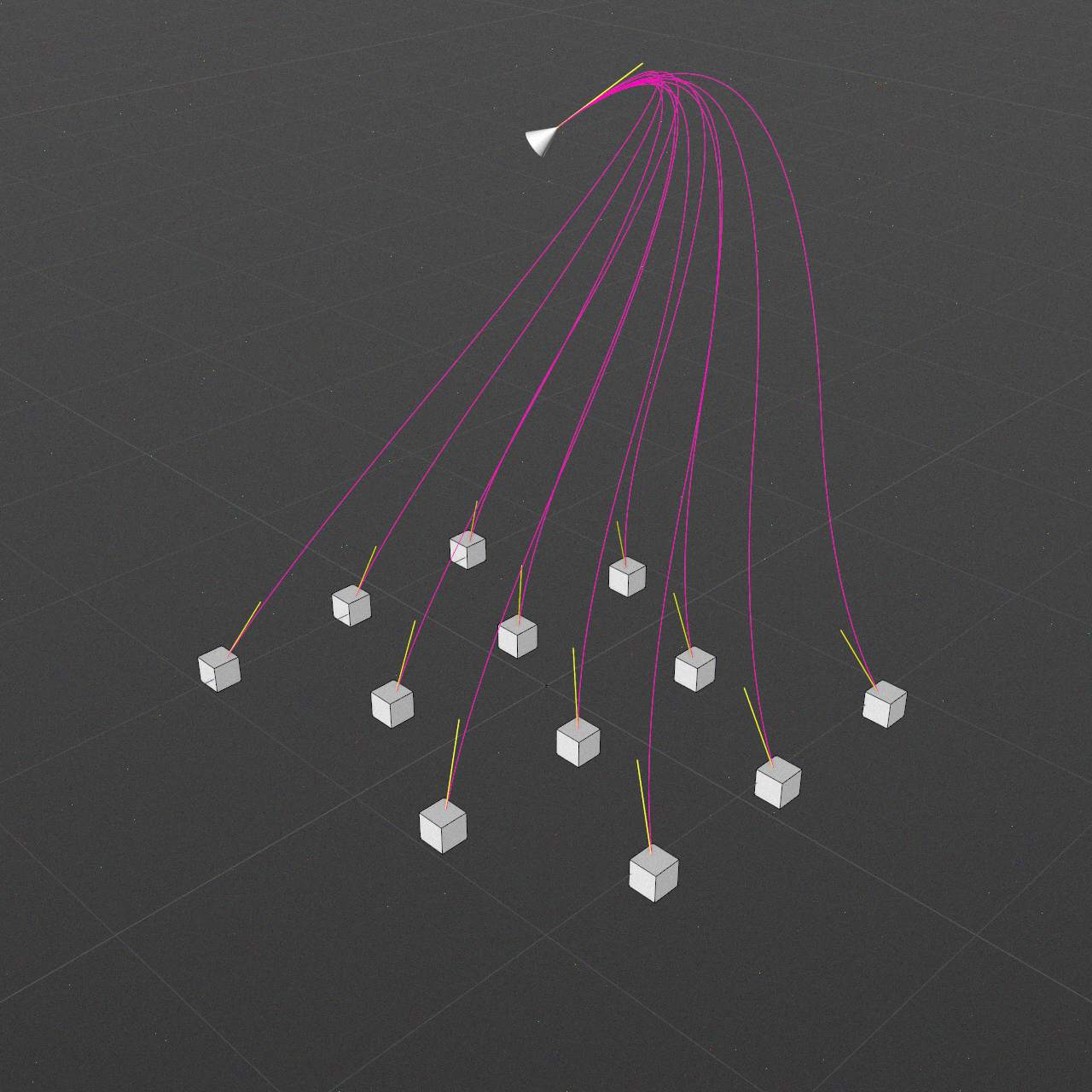
Strength: 30
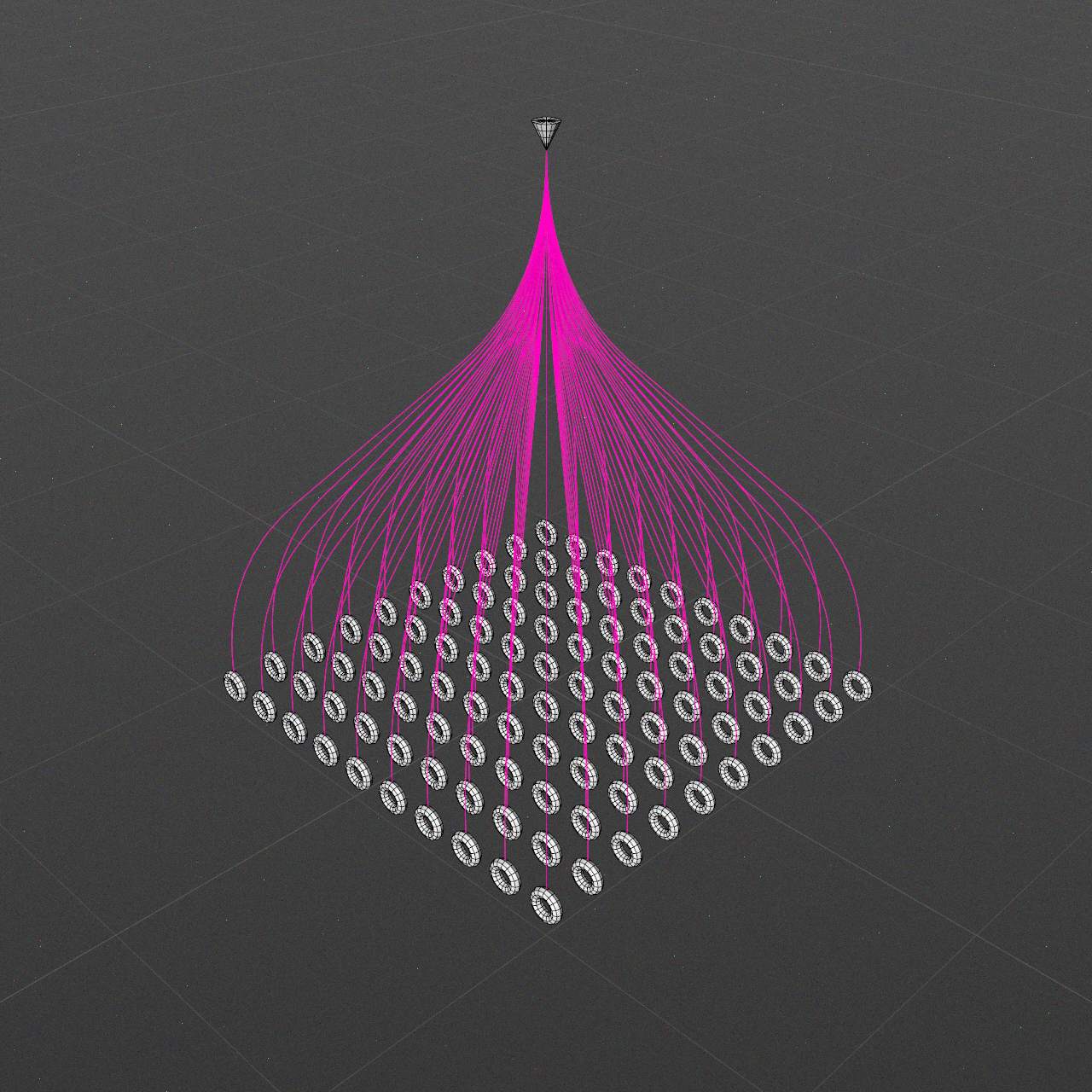
-
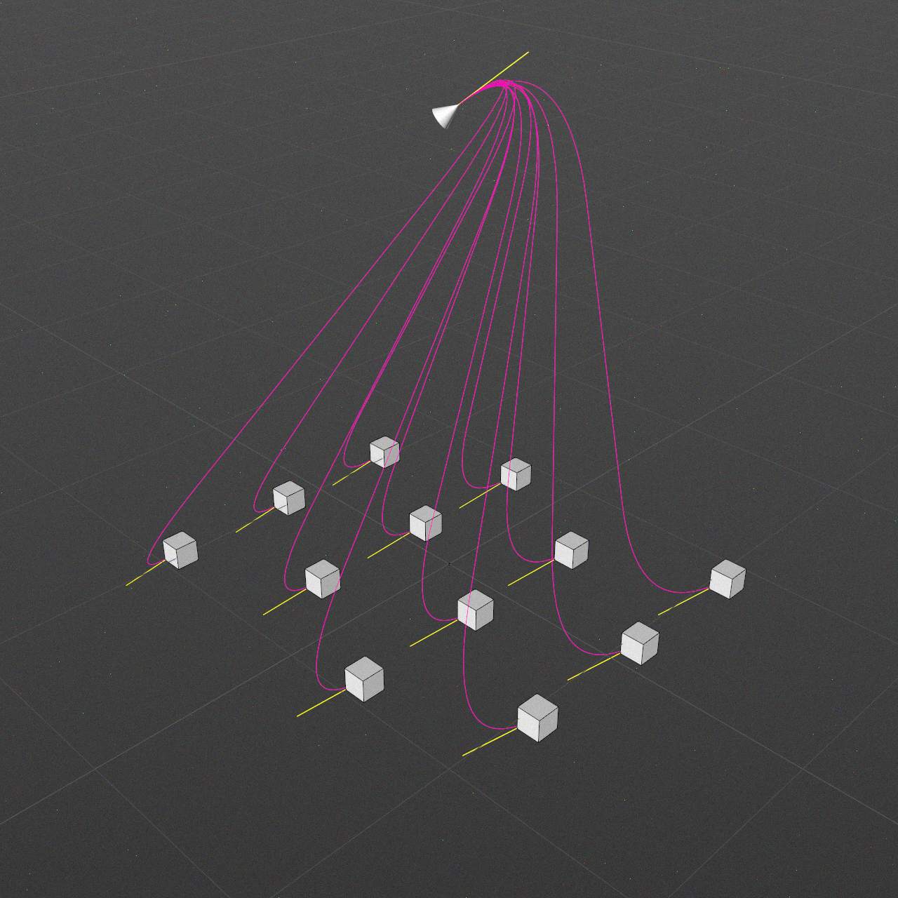
Strength: 120
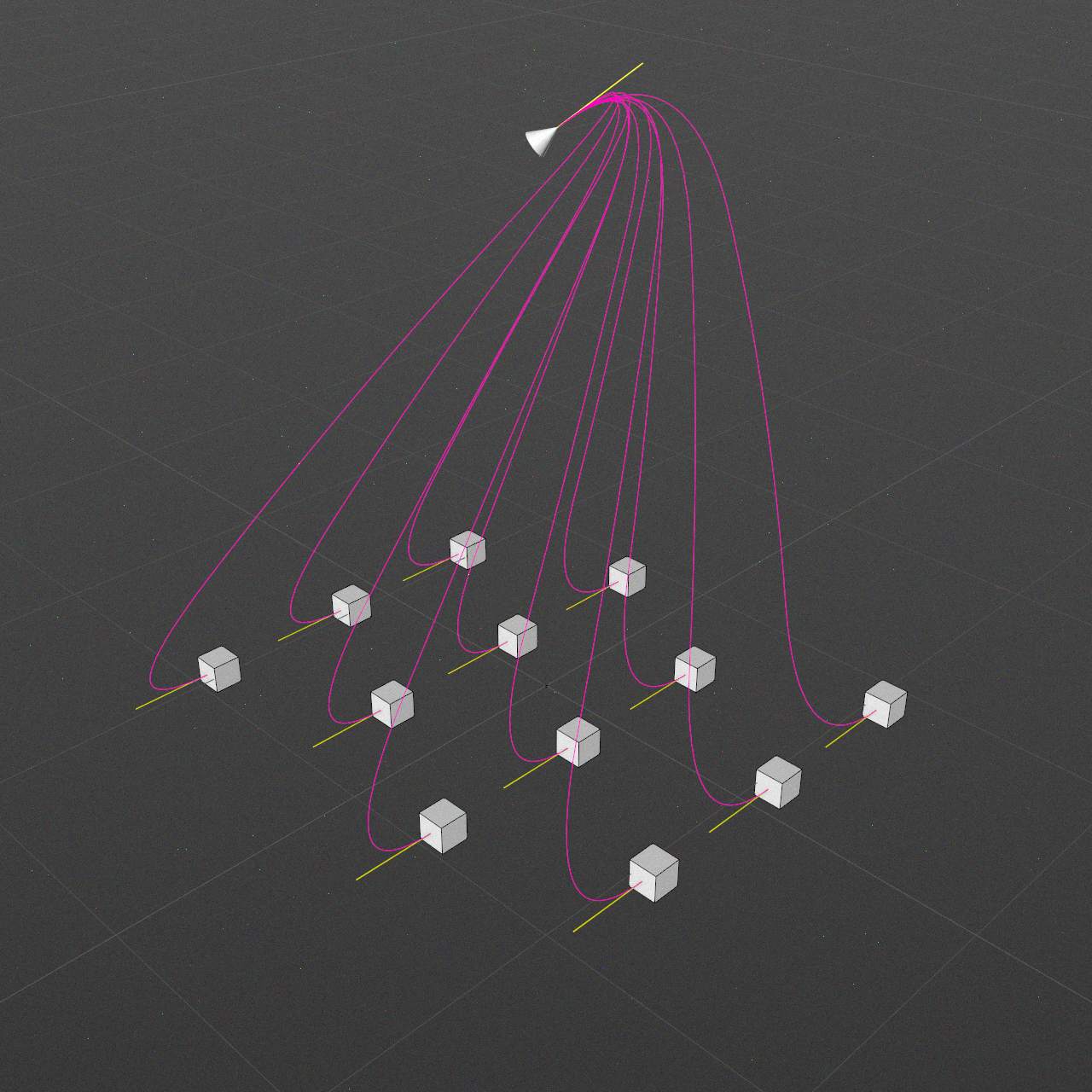
Gravity might have inverted direction.
Or even abstract one.
Re-spline
Might be useful to finetune spline shape (strong gravity might produce weird looking curves)
Enable
Type, Interpolation, Number, Angle, Maximum length
Rest of the parameters same as in the Spline tab.
-
Disabled
-
B-Spline / Uniform / 2
-
Disabled
-
B-Spline / Uniform / 8
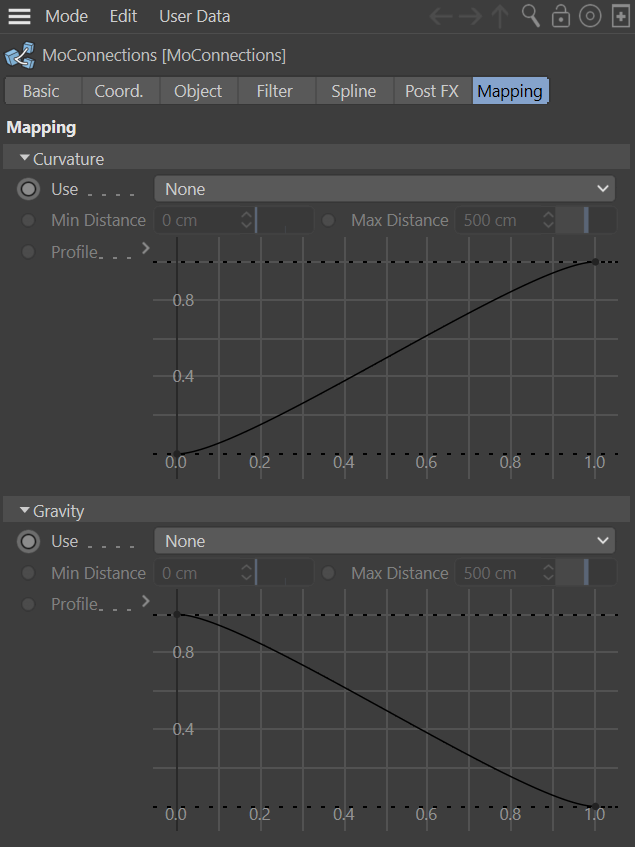
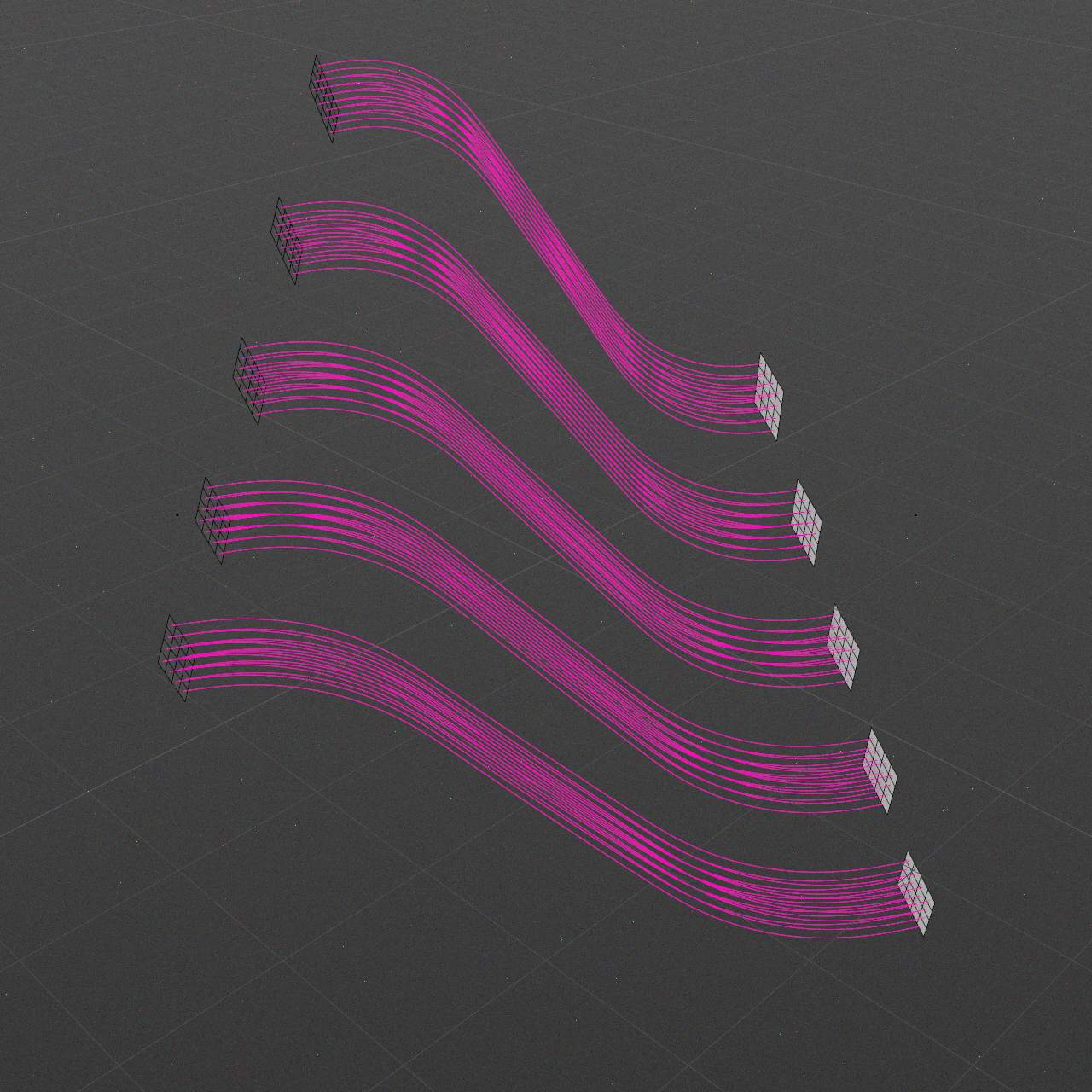
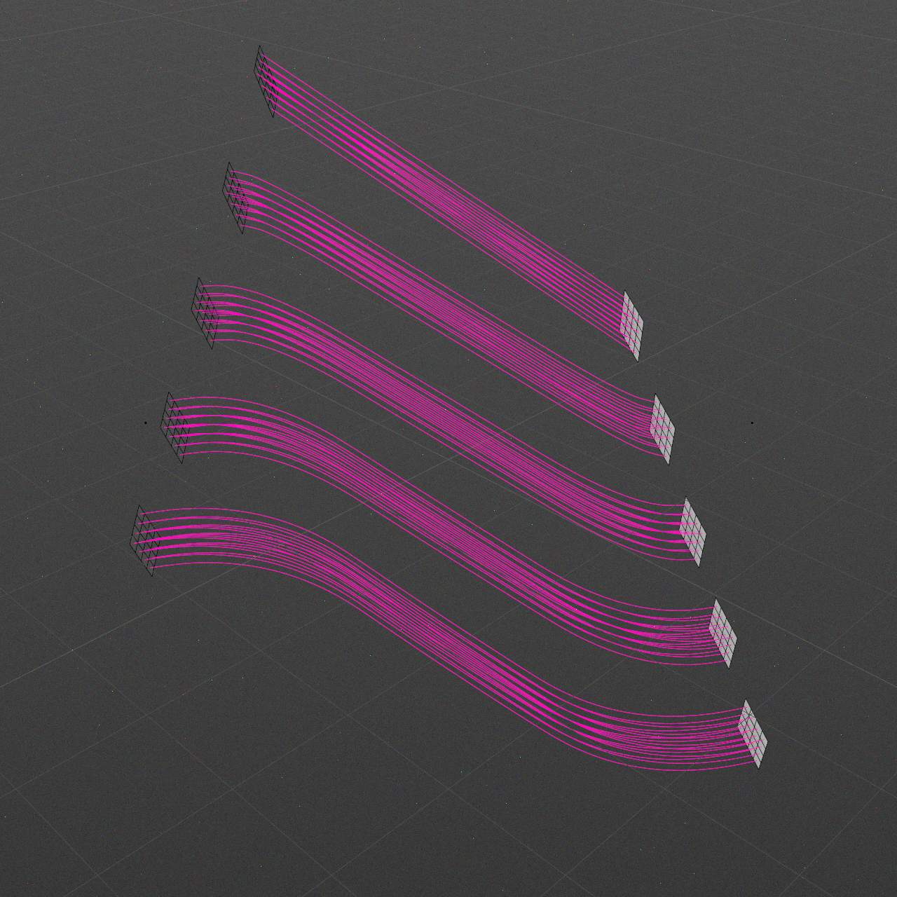
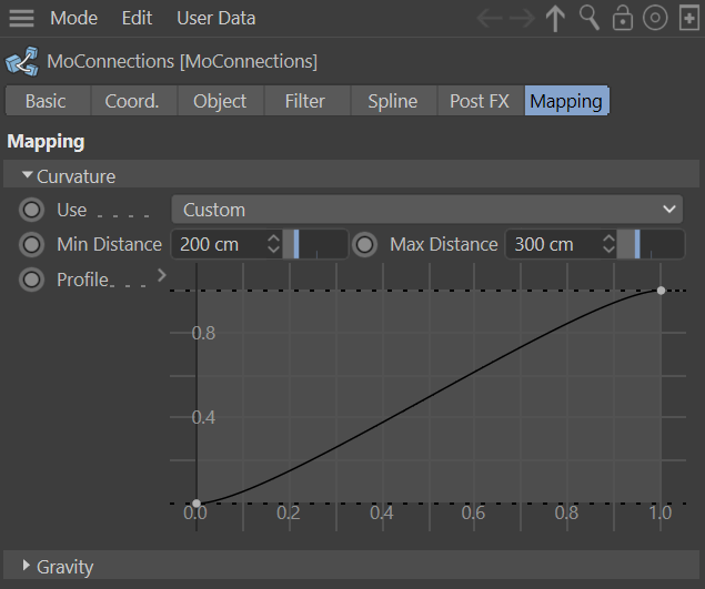
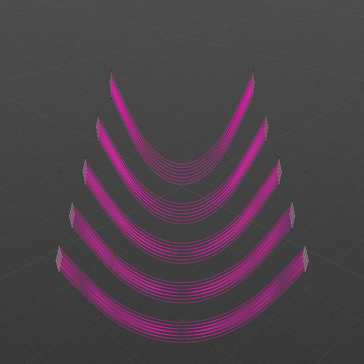
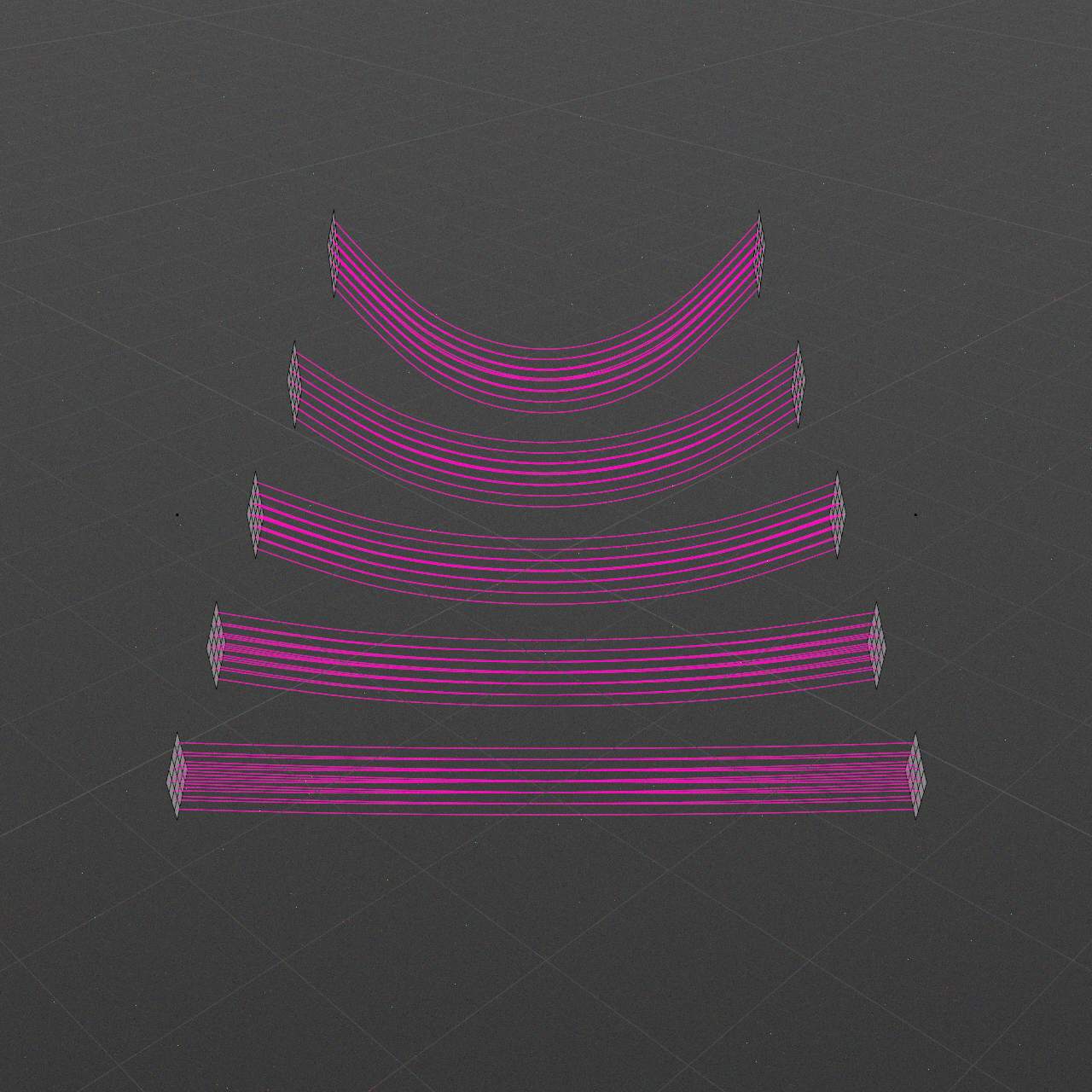
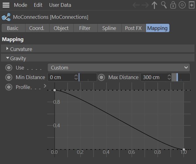
Mapping
Mapping brings control over individual spline shape based on entries relative distance.
Curvature
This option controls Curvature strength.
Use
None option provides no mapping.
As Curvature, As Gravity options share chosen mapping.
Custom option allows to set mapping profile.
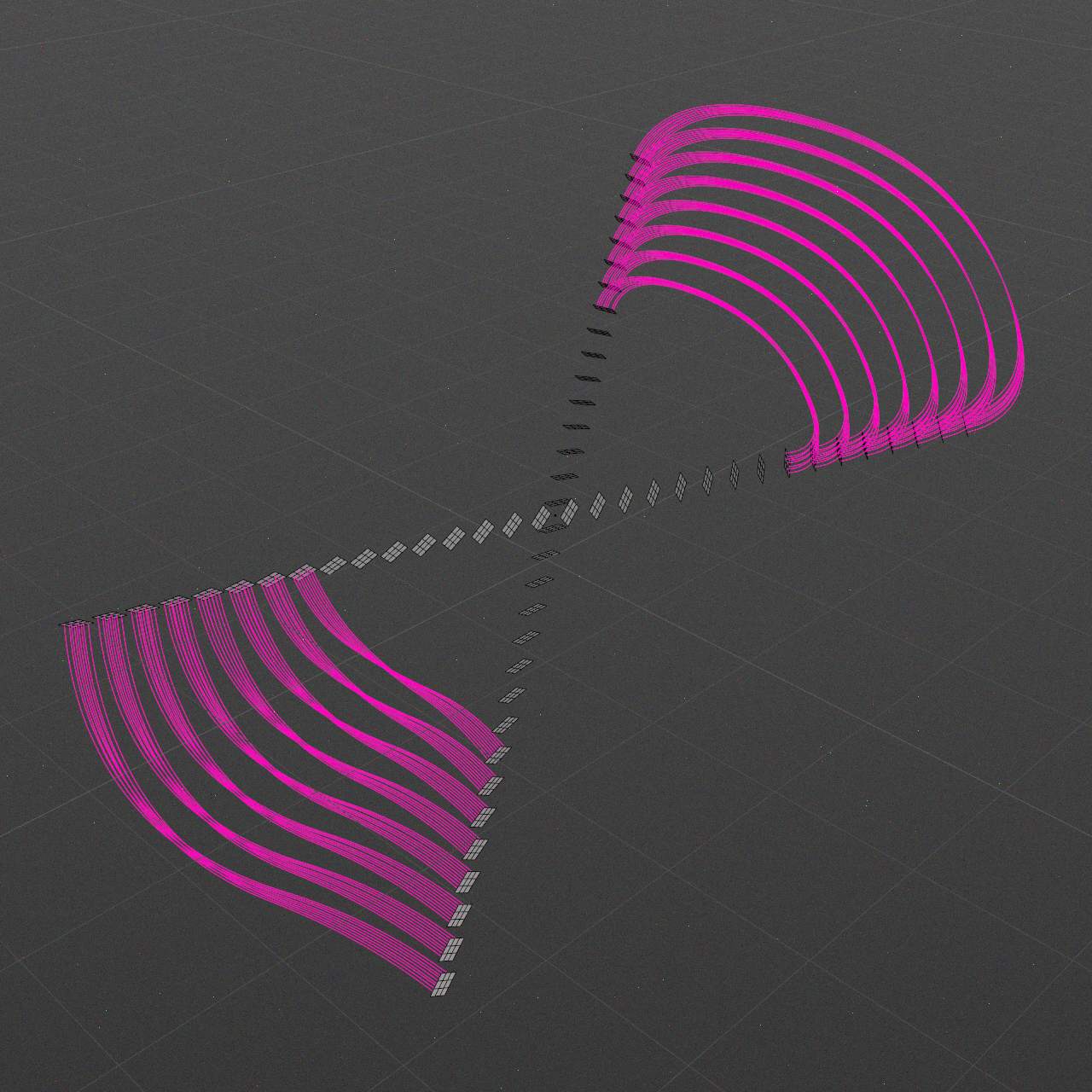
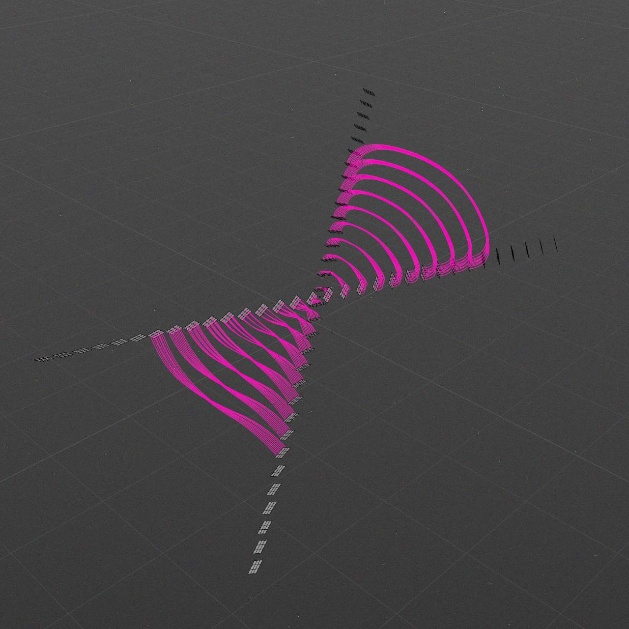
Min Distance
0..-∞ m
Starting distance value, at which profile graph begins.
Max Distance
0..-∞ m
Ending distance value, at which profile graph ends.
Profile
This graph maps distance from min to max.
Gravity
This option controls Gravity strength.
Use
None option provides no mapping.
As Curvature, As Gravity options share chosen mapping.
Custom option allows to set mapping profile.
Min Distance
0..-∞ m
Starting distance value, at which profile graph begins.
Max Distance
0..-∞ m
Ending distance value, at which profile graph ends.
Profile
This graph maps distance from min to max.